You are using an out of date browser. It may not display this or other websites correctly.
You should upgrade or use an alternative browser.
You should upgrade or use an alternative browser.
Blender, My LX450/FZJ80 + FJ45esk + GM + Land Rover crazy concoction
- Thread starter Metcalf
- Start date
Metcalf
Expedition Leader
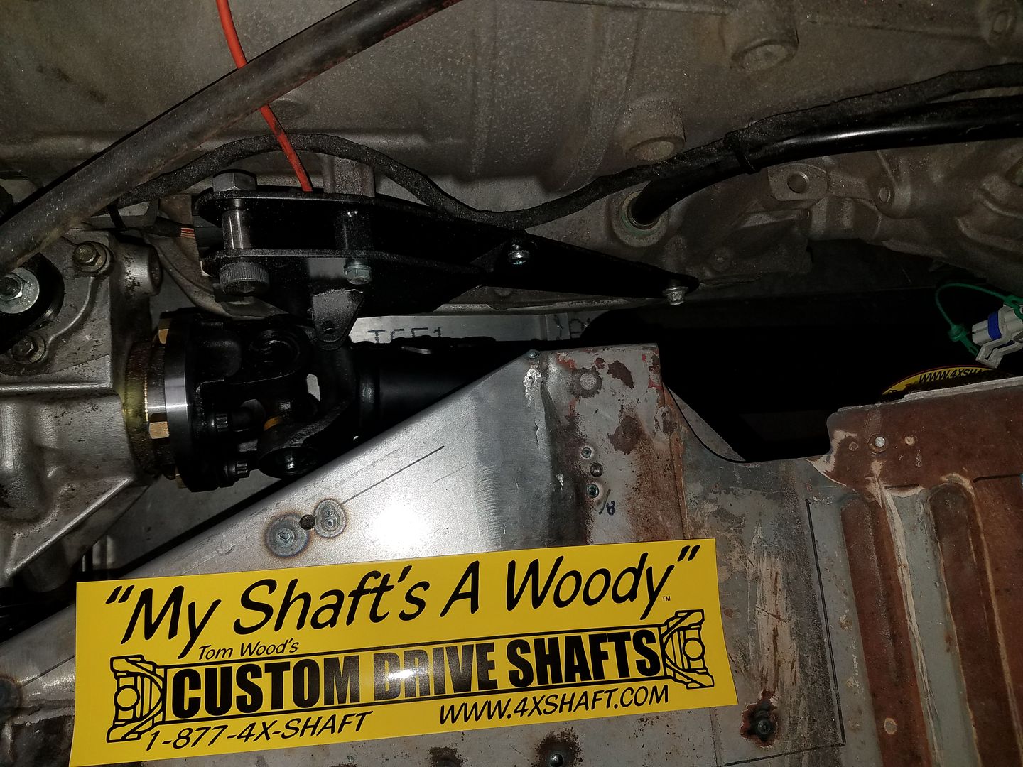
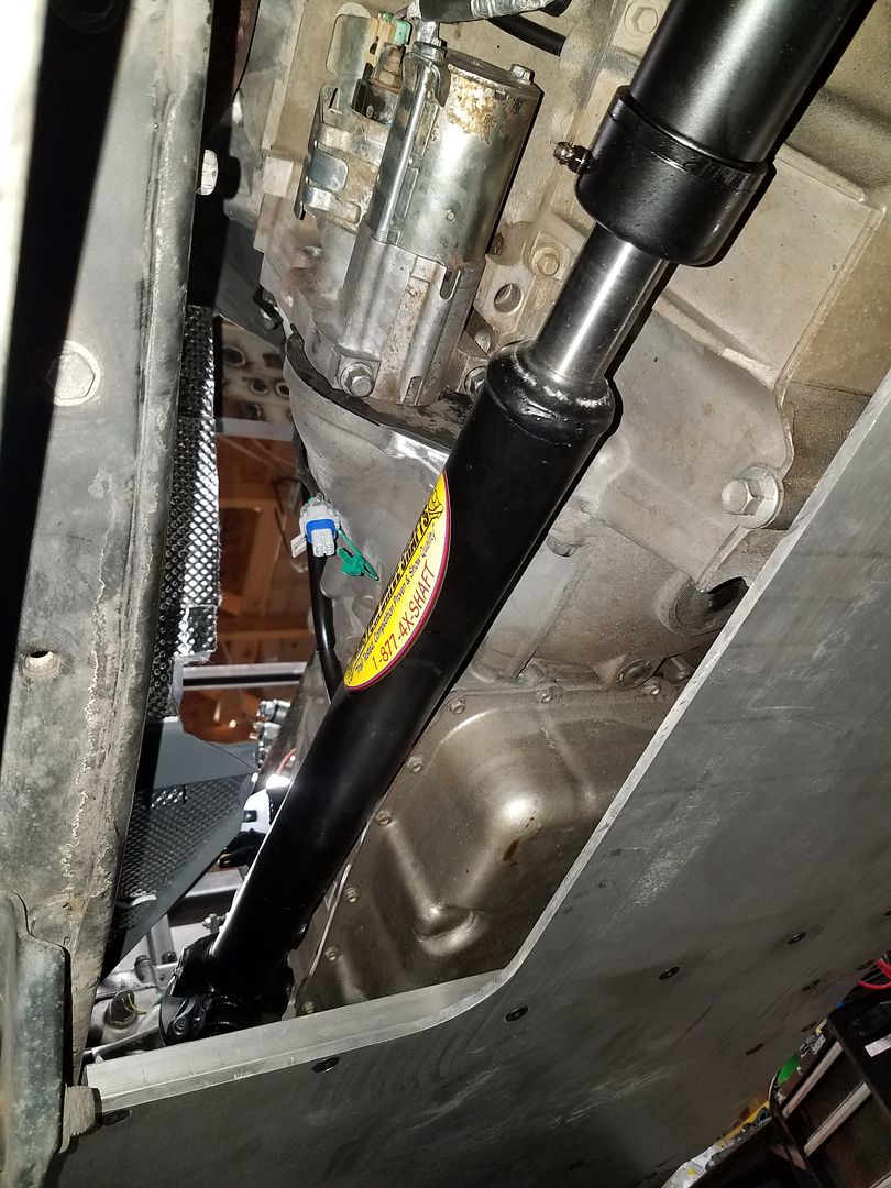
Mini bite on the #LX45 tonight with the front driveshaft install. A big thanks to Tom Woods for building exactly what I needed. This truck is neat because I was able to position the powertrain so I could have equal length front and rear shafts. A common spare will fit either end. All ujoints are also 1310 so I can use a common easy to find spare for that also. I love how high the front shaft is up inside the chassis with the high pinion diff. I won't have to worry too much about rock damage.


Metcalf
Expedition Leader
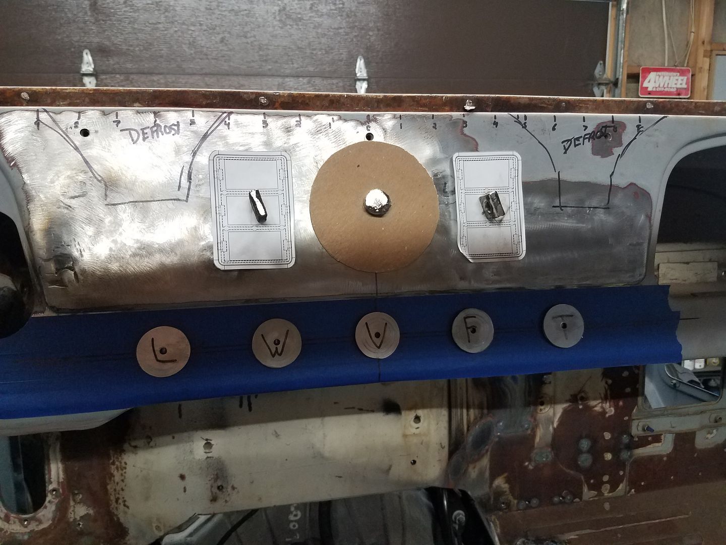
Before I cut big holes in the dash again, I wanted to take a bit of time to do a final scale layout and check a few things.
This is the majority of the control center for the #LX45.
-Round thing in the center/middle, is a marine grade round stereo unit.
-The left Carling switch bank will be the lockers ( Front, center, rear )
-The right Carling switch bank will be the On board air, suck down winch, and a USB power port
-The round knobs are Lights, Wipers, Cowl Vent, Heater Fan, Heater Temp
Shop tip...
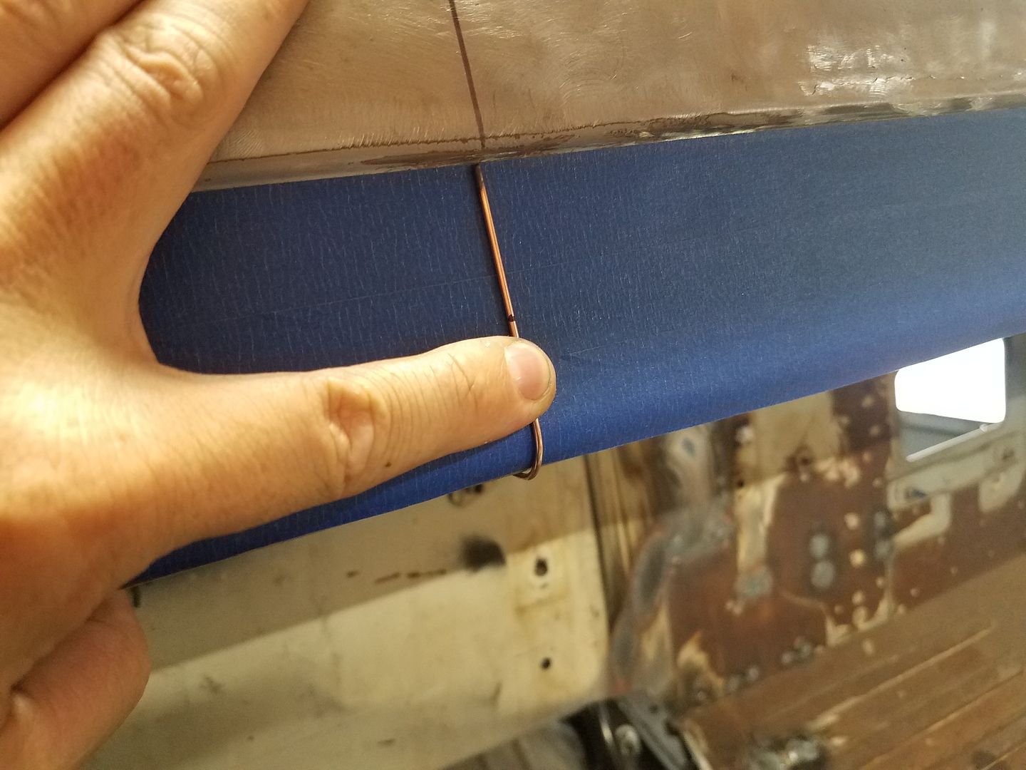
I formed a piece of TIG filler from the step around the bottom flange of the dash. It was cut to the length of the wrap around flange.
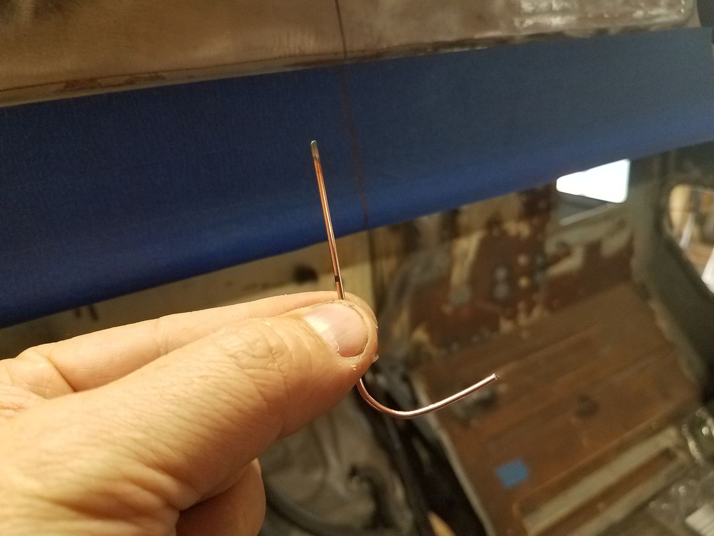
This is an accurate model of the dash profile where the switches/knobs will go.....
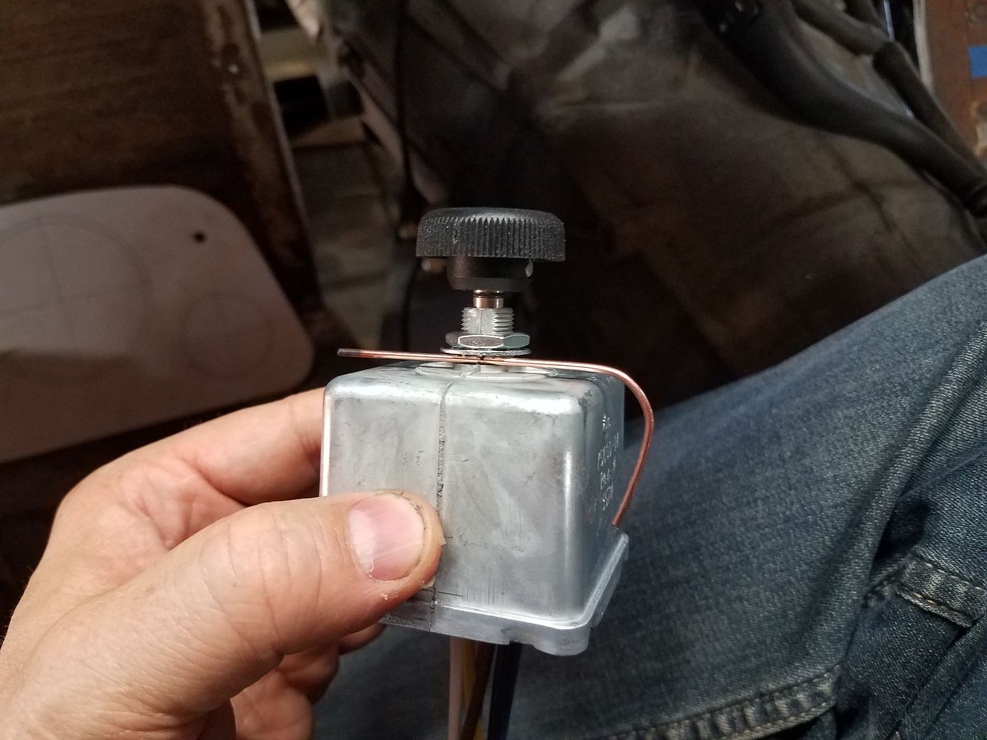
This is the largest switch I have going in the dash in that area ( wiper delay switch with wash function ). I used the template wire to judge the minimum position for the switch body on the face of the dash. Basically I didn't want to drill the hole and not be able to fit the box! That would make me grumpy.
That information was transferred over the dash for a horizontal datum line.
I was then able to test the spacing of the knobs for looks and clearance from switch body to switch body. I settled on a 3" spacing for the knobs. I will remake the knobs so they all match in this area eventually. Maybe have them 3d printed...
Metcalf
Expedition Leader
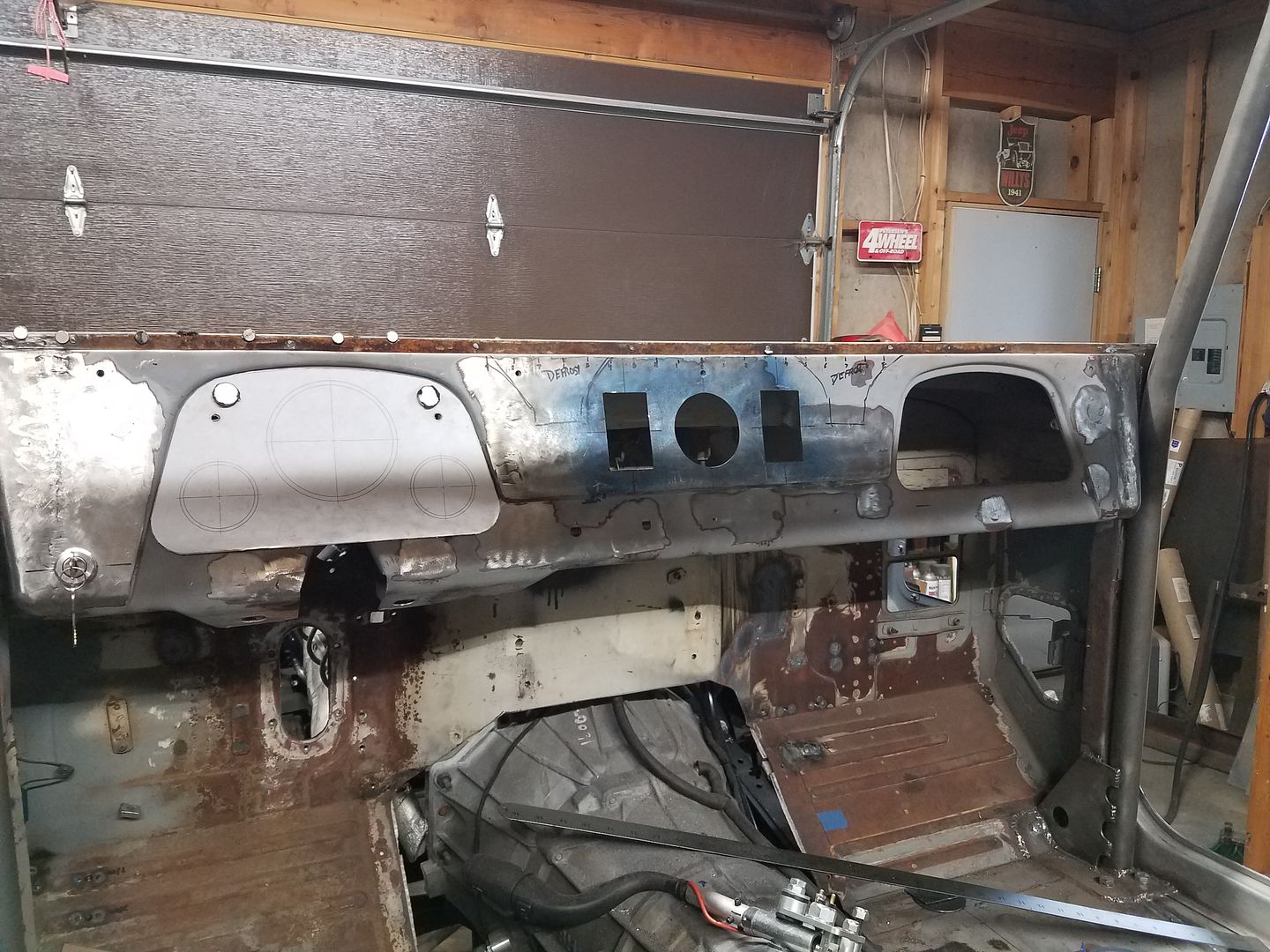
Cutting all sorts of holes in the #LX45 dash today. I swear, can someone just pick a standard hole type already for switches! All the small holes for the key, lights, wipers, heater, etc where all a different style. I like working on my filing skills but come on. I still need a heater temp valve and to rebuild the relay rod for the cowl vent. The marine stereo worked out sweet along with the 3x Carling switch pods. I suggest not clipping the Carling pods in till you are ready to leave them. It took me like 20 minutes to get that sucker back out.
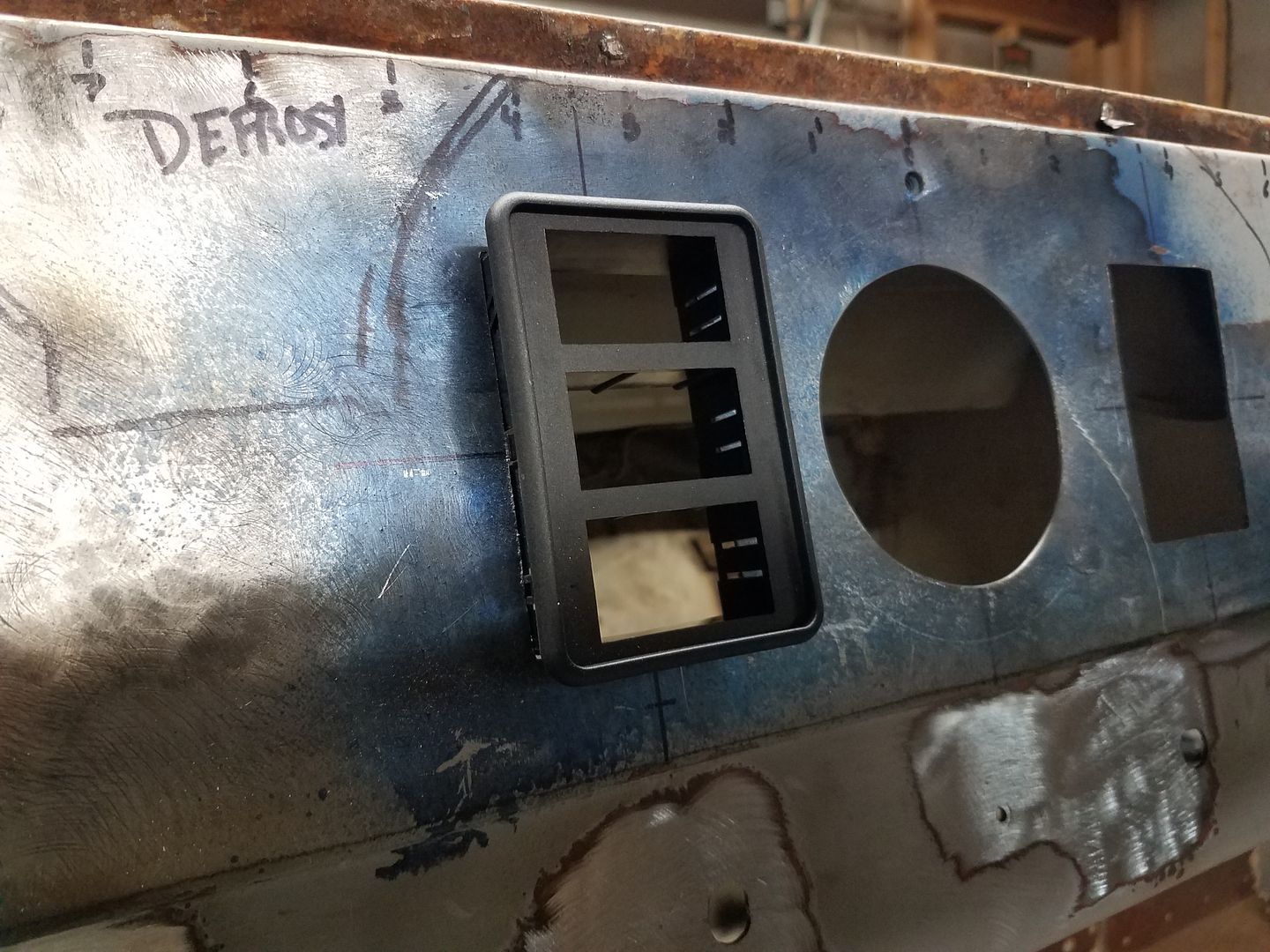
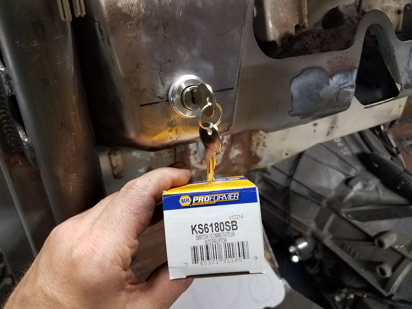
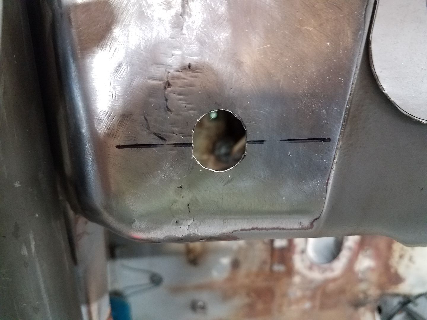
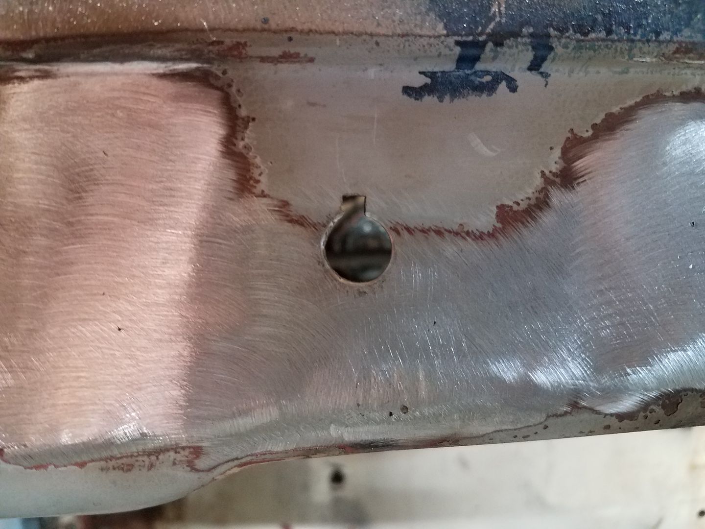
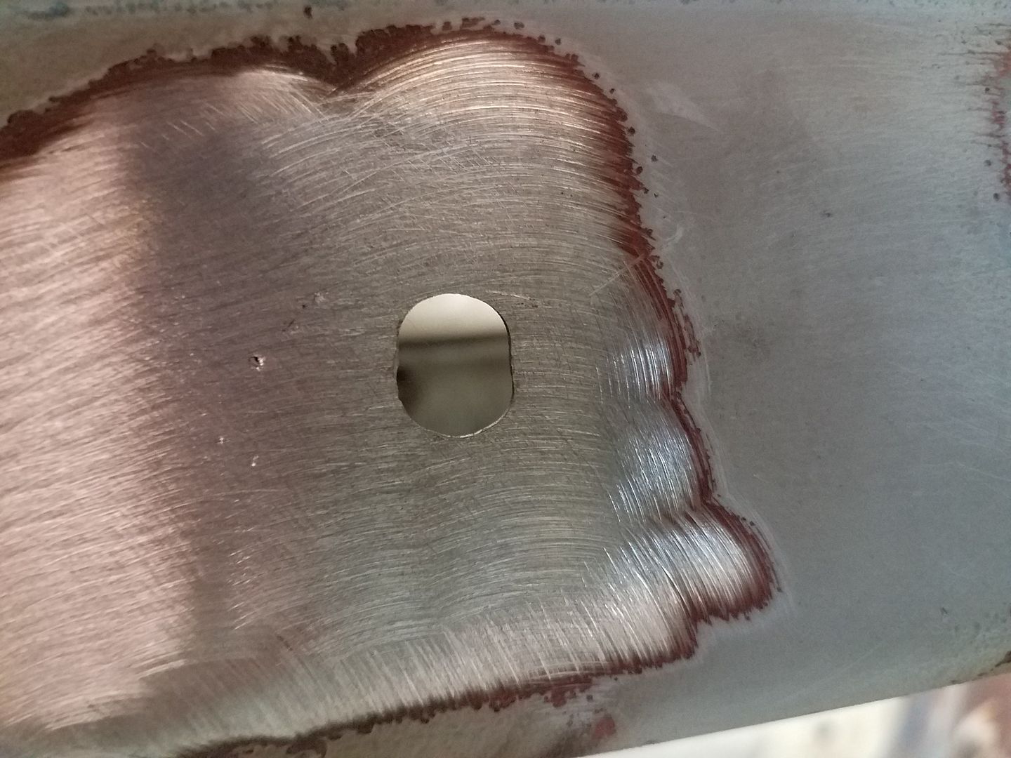
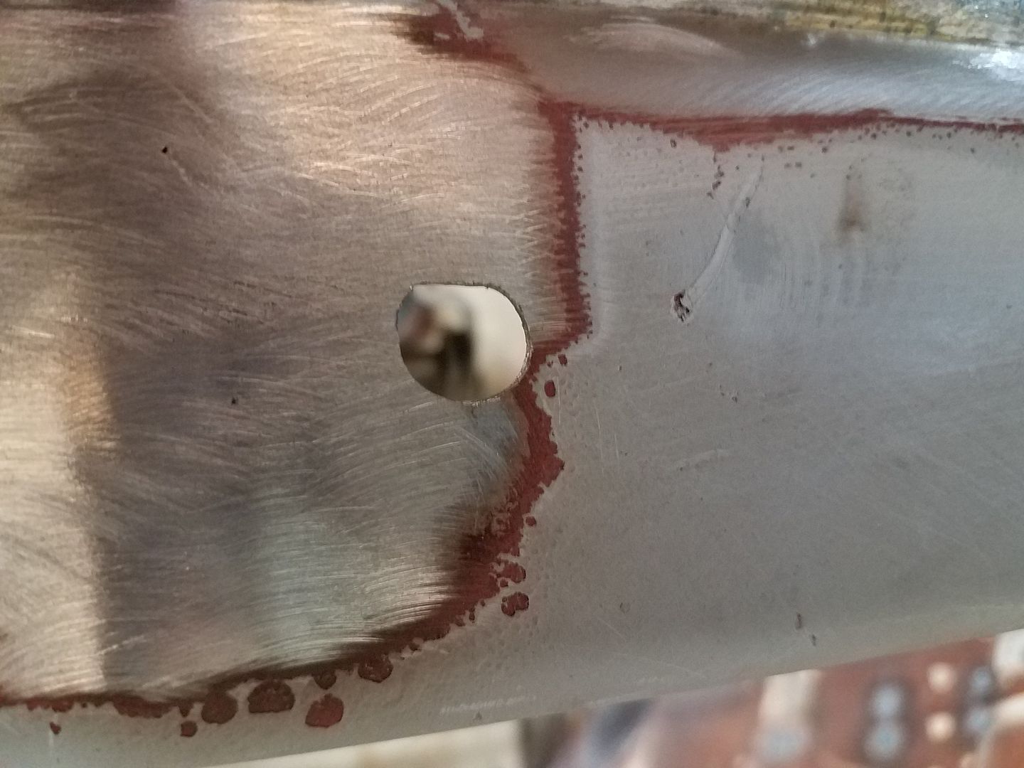
A note on the different holes for the switches. They where all different, but they where all made with a drill bit, a few files, and some time. While it was a complete pain, it was nice to have it done right so they won't rotate in use.
Just take your time, don't try to over think it too much.
Metcalf
Expedition Leader
Metcalf
Expedition Leader
Been slacking and a small set back along the way...
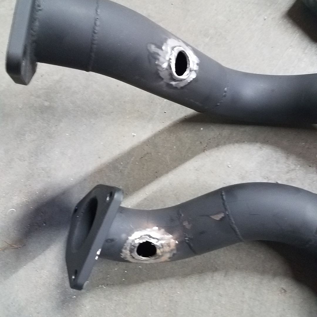
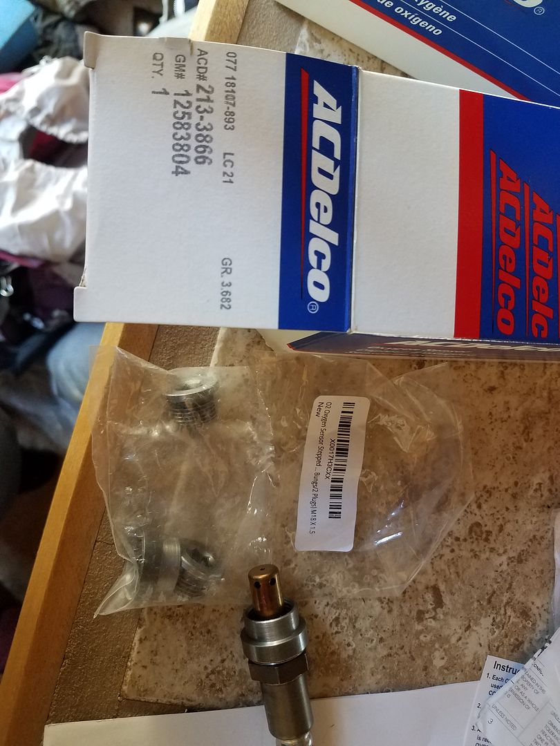
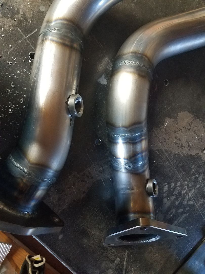
I ended up welding in the O2 bungs with the plugs installed for some reason. I messed up something in the welding and the plugs bonded to the bungs. I stripped them out trying to remove them. I ended up having to cut and grind them out. Non fun.
Oh, and I didn't find that out till the exhaust was installed. Total bummer and waste of time!
I ordered another pair of bungs, while I waited for those I did a few other things.
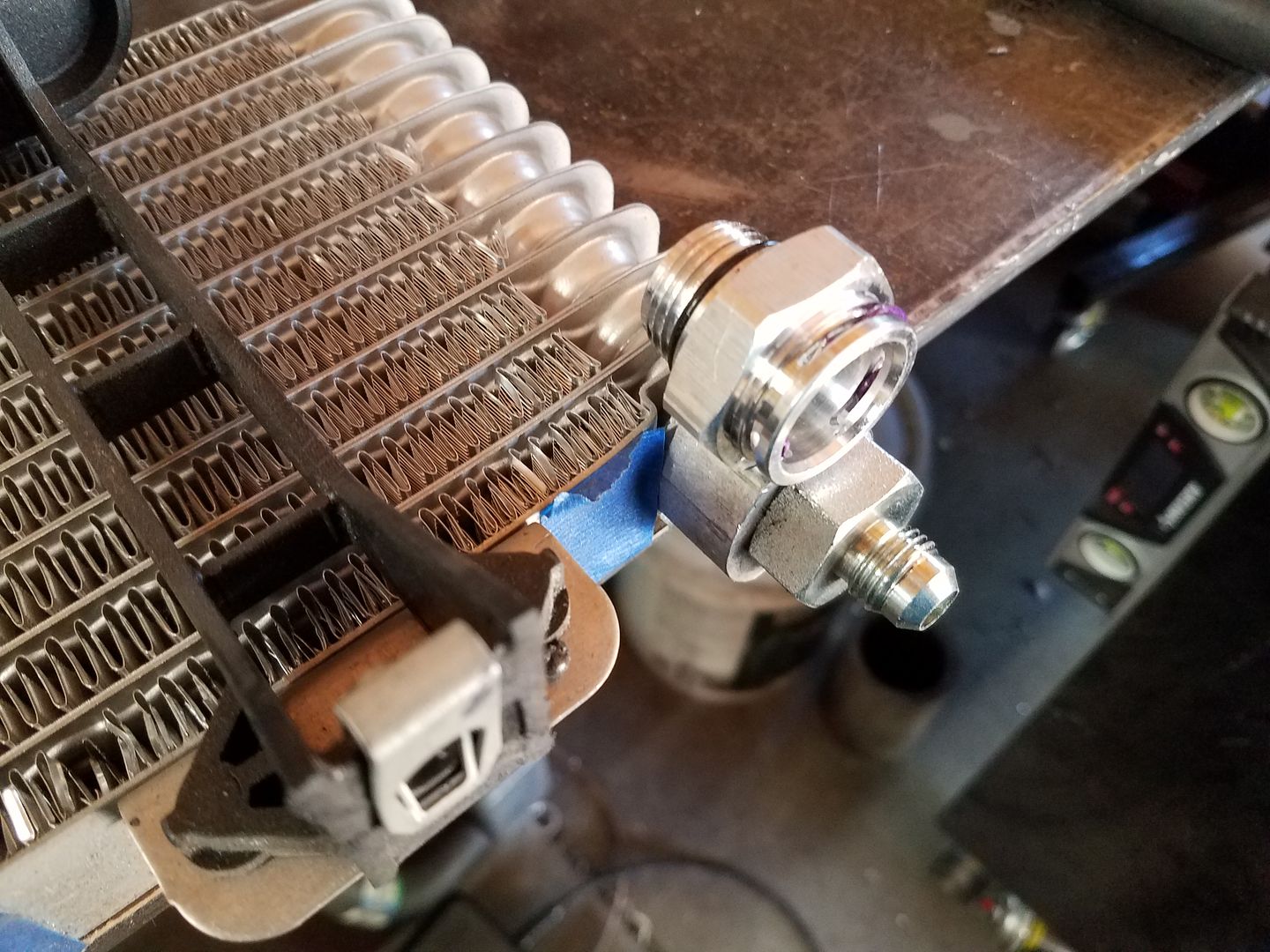
I found some off the shelf o-ring to jic fittings for the transmission cooler to replace the GM factory version. No mods needed to the cooler. This will make a future replacement easy. This will also make hoses easy.
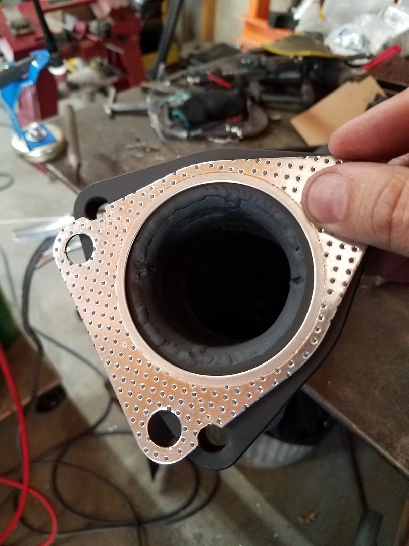
I was able to slightly mod a factory drivers side gasket to work on the passenger side exhaust manifold also, instead of the factory donut.
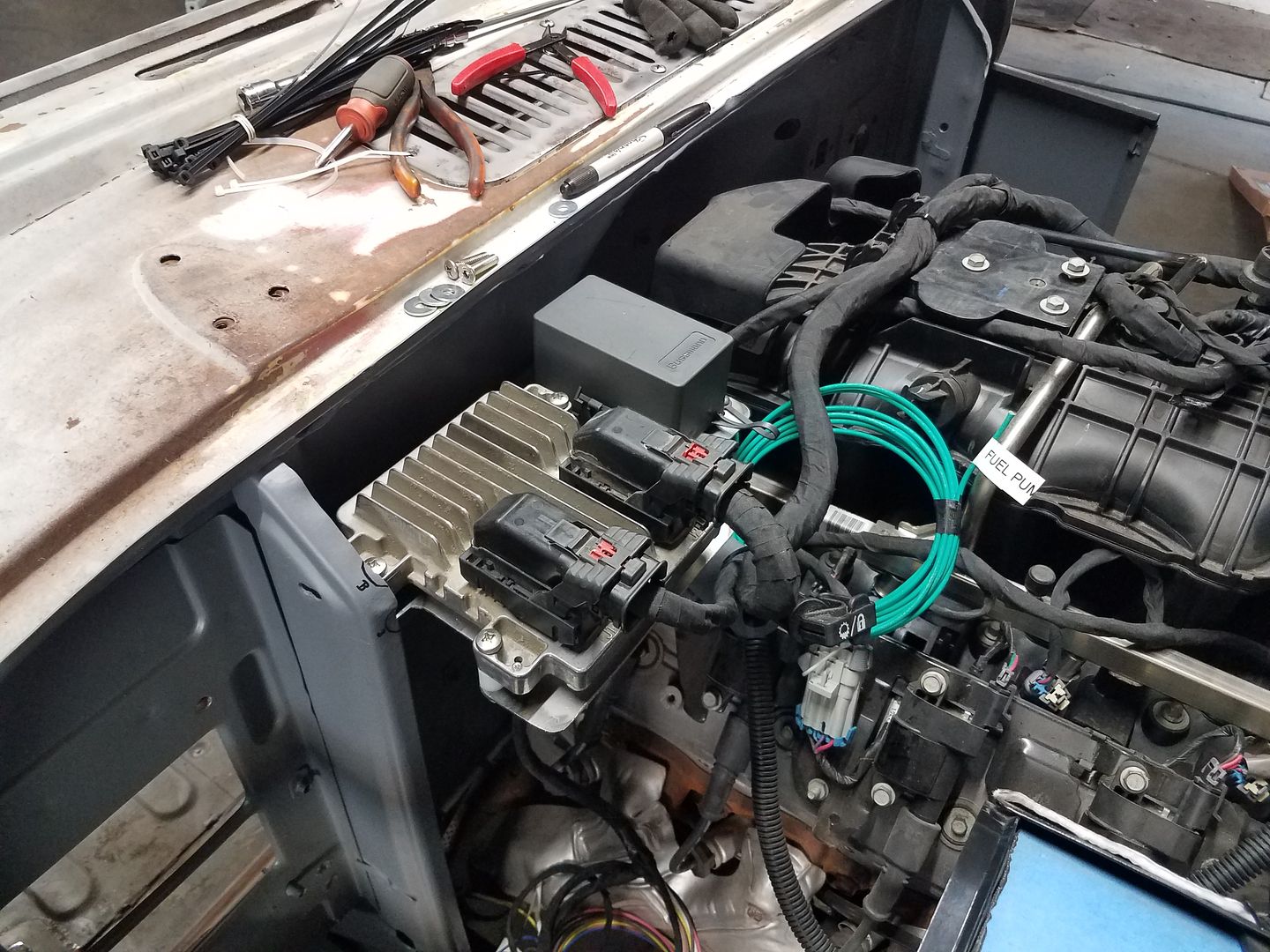
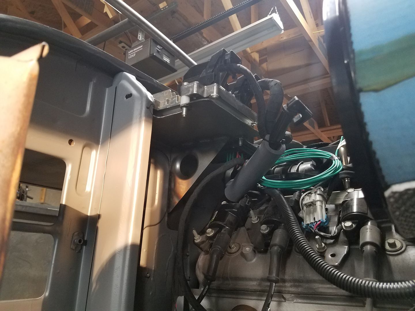
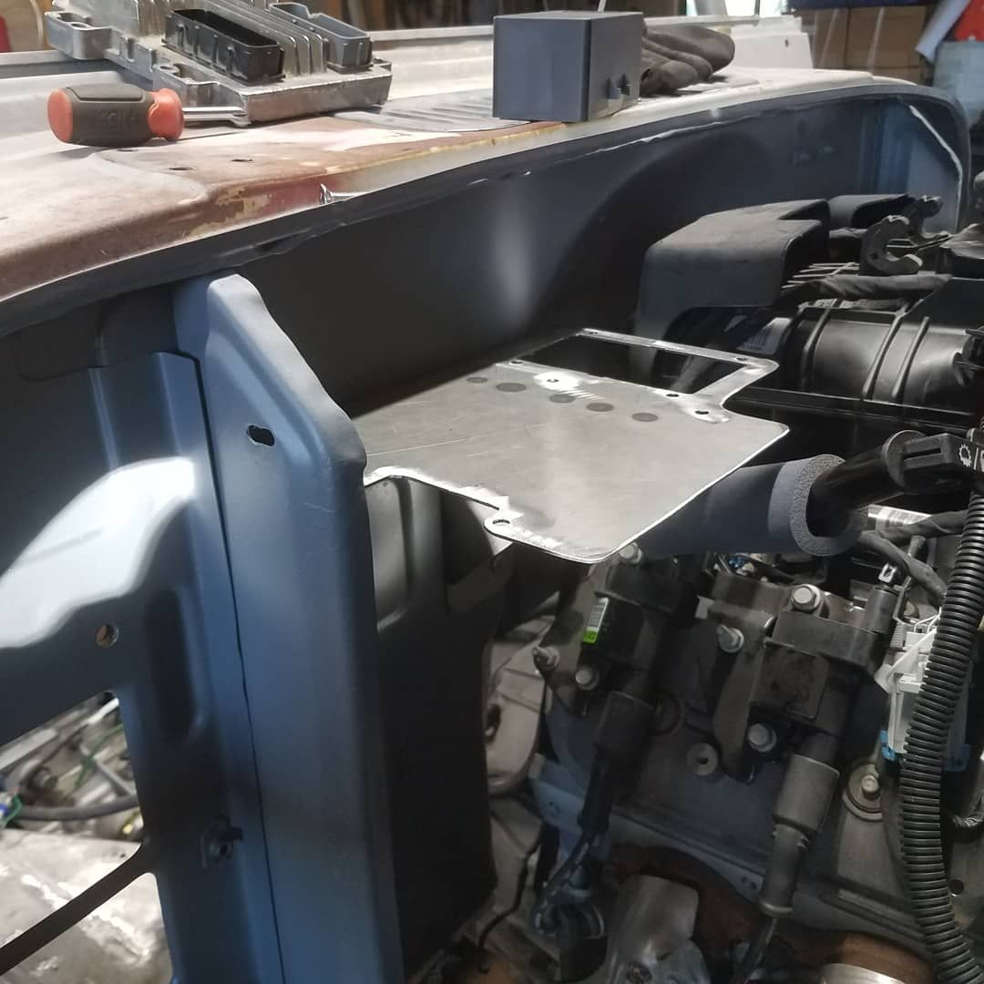
I built a bracket that bolted to some existing threaded holes on the firewall on the passenger side. It holds the engine fuse/relay box along with the ECM. I'm trying to keep things off the fenders completely to make working on things a bit easier.
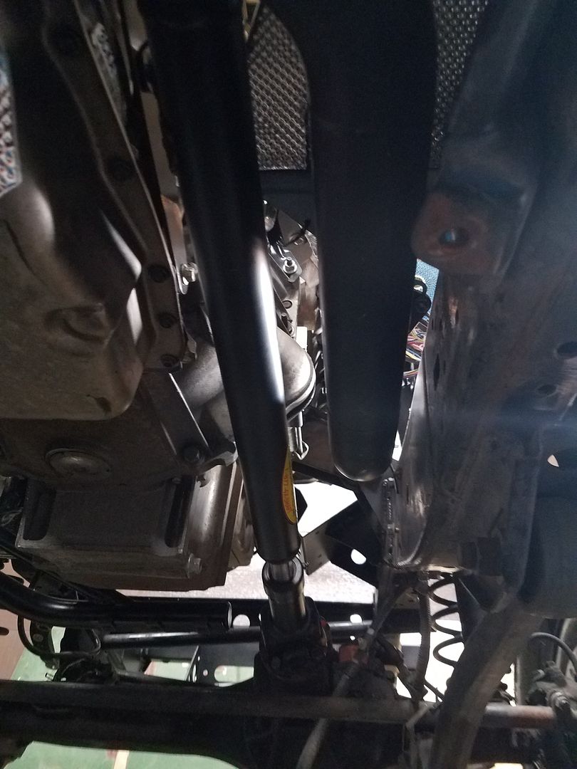
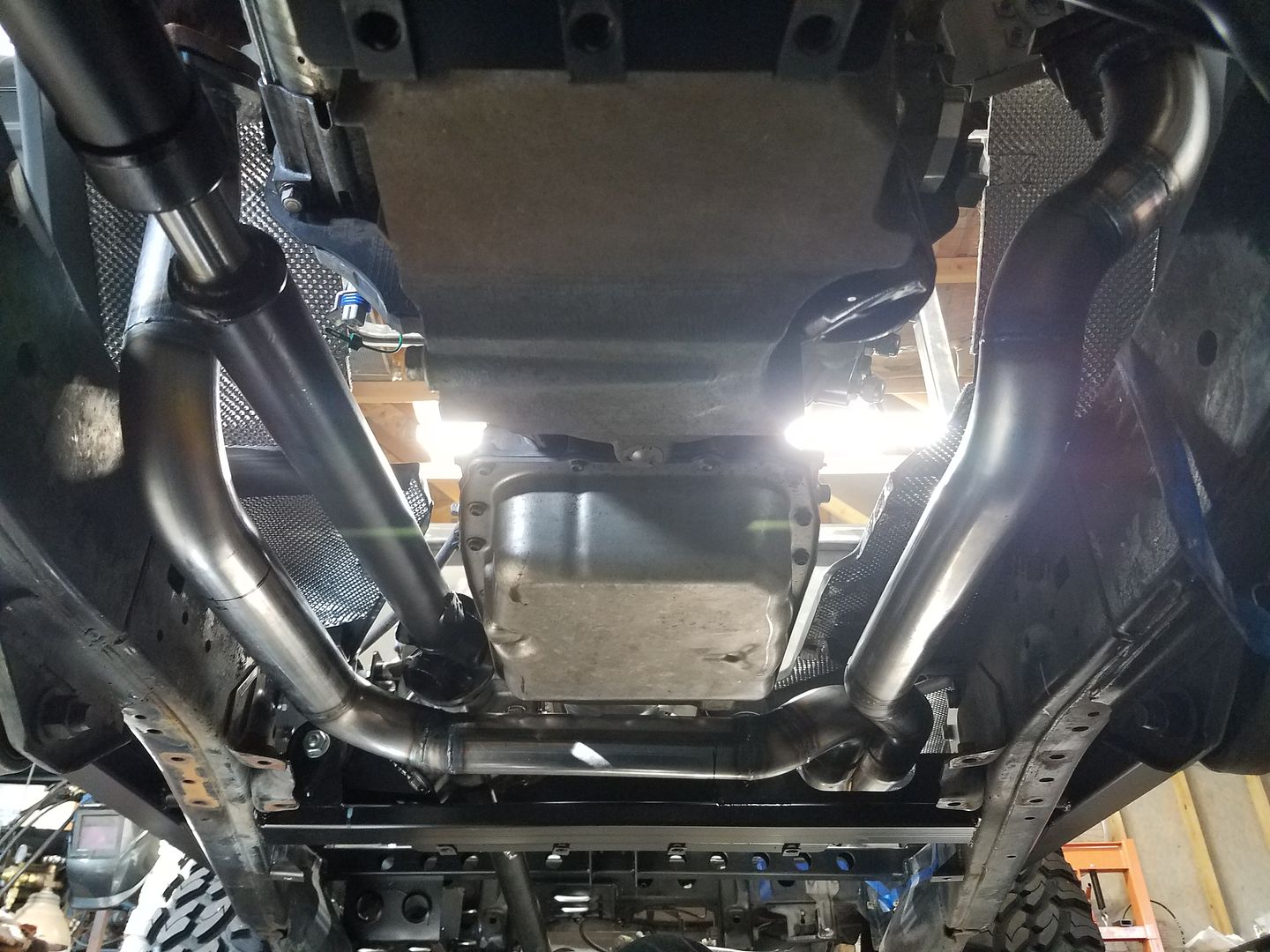
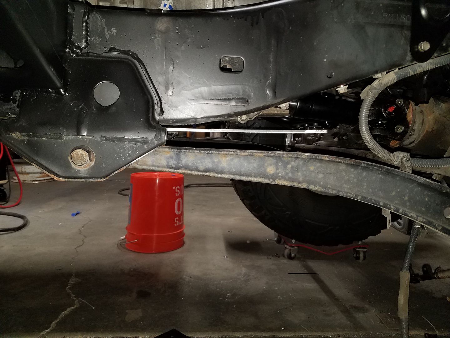
Once I got the new O2 bungs in, I welded those up, with no issues this time. I was able to finally install the y-pipe in the vehicle along with the new O2 sensors. This is a bad picture of the clearance the front driveshaft has on the passenger side down tube. I had a few people ask about the clearance in that area.

I ended up welding in the O2 bungs with the plugs installed for some reason. I messed up something in the welding and the plugs bonded to the bungs. I stripped them out trying to remove them. I ended up having to cut and grind them out. Non fun.
Oh, and I didn't find that out till the exhaust was installed. Total bummer and waste of time!
I ordered another pair of bungs, while I waited for those I did a few other things.

I found some off the shelf o-ring to jic fittings for the transmission cooler to replace the GM factory version. No mods needed to the cooler. This will make a future replacement easy. This will also make hoses easy.

I was able to slightly mod a factory drivers side gasket to work on the passenger side exhaust manifold also, instead of the factory donut.


I built a bracket that bolted to some existing threaded holes on the firewall on the passenger side. It holds the engine fuse/relay box along with the ECM. I'm trying to keep things off the fenders completely to make working on things a bit easier.

Once I got the new O2 bungs in, I welded those up, with no issues this time. I was able to finally install the y-pipe in the vehicle along with the new O2 sensors. This is a bad picture of the clearance the front driveshaft has on the passenger side down tube. I had a few people ask about the clearance in that area.
locrwln
Expedition Leader
Been slacking and a small set back along the way...
I ended up welding in the O2 bungs with the plugs installed for some reason. I messed up something in the welding and the plugs bonded to the bungs. I stripped them out trying to remove them. I ended up having to cut and grind them out. Non fun.
Oh, and I didn't find that out till the exhaust was installed. Total bummer and waste of time!
I ordered another pair of bungs, while I waited for those I did a few other things.
I did the same exact thing on my 4.3 conversion into my '85 4Runner. Had everything just so and had to pull it all back out, chop out the old, install the new and re-install everything. Fun (and very frustrating) times.
Jack
Metcalf
Expedition Leader
More things....
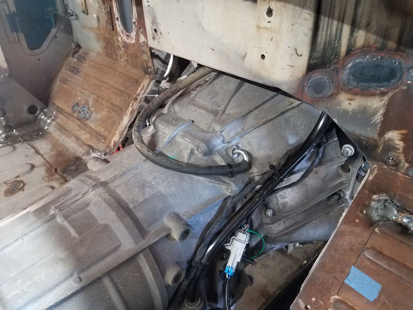
Re-plumbed the vent tube for the 6L80E transmission up to behind the intake on engine. That is pretty high on this chassis....
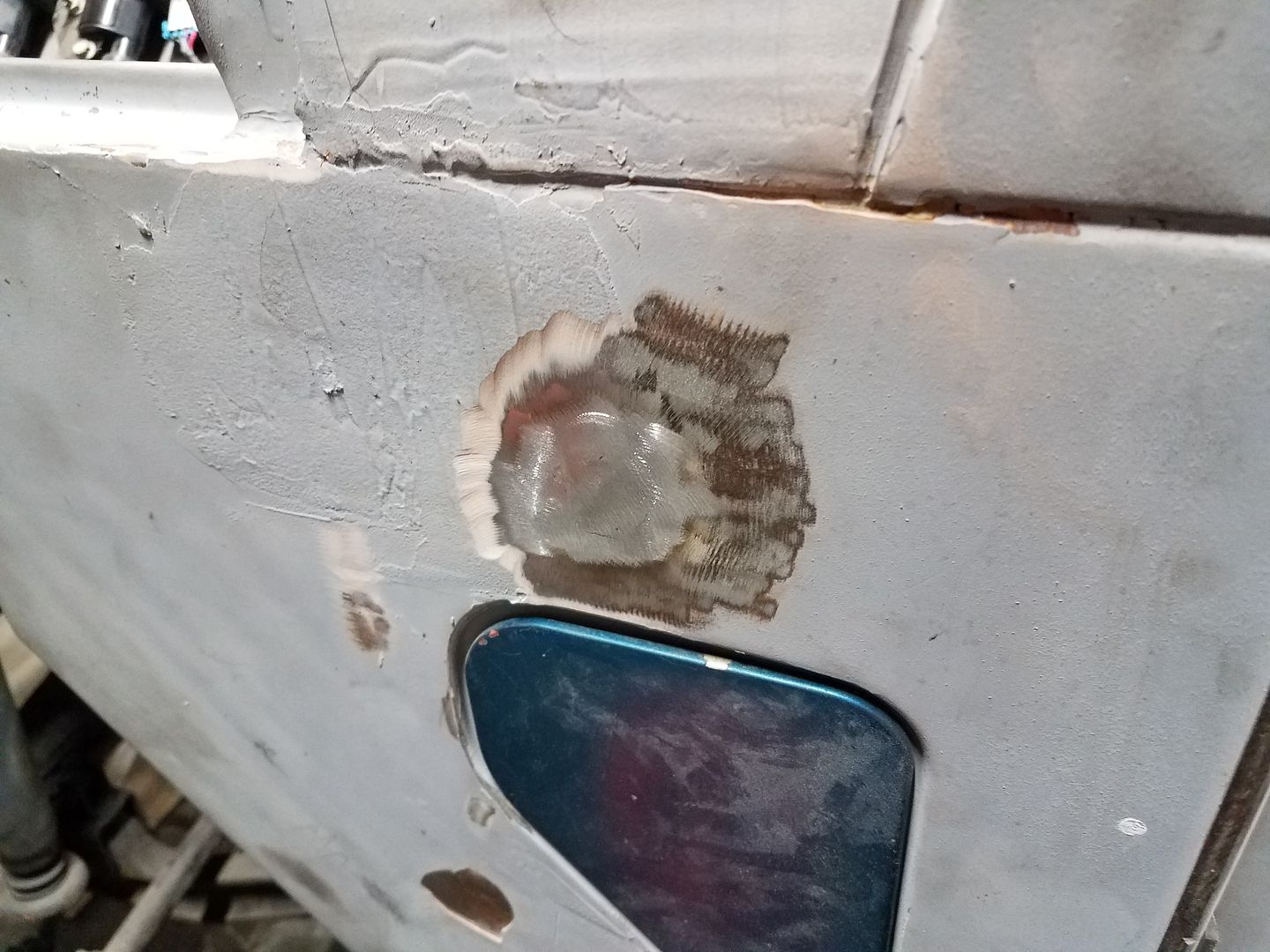
Worked on making some hole patch seams disappear....
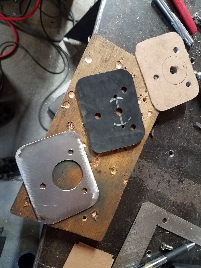
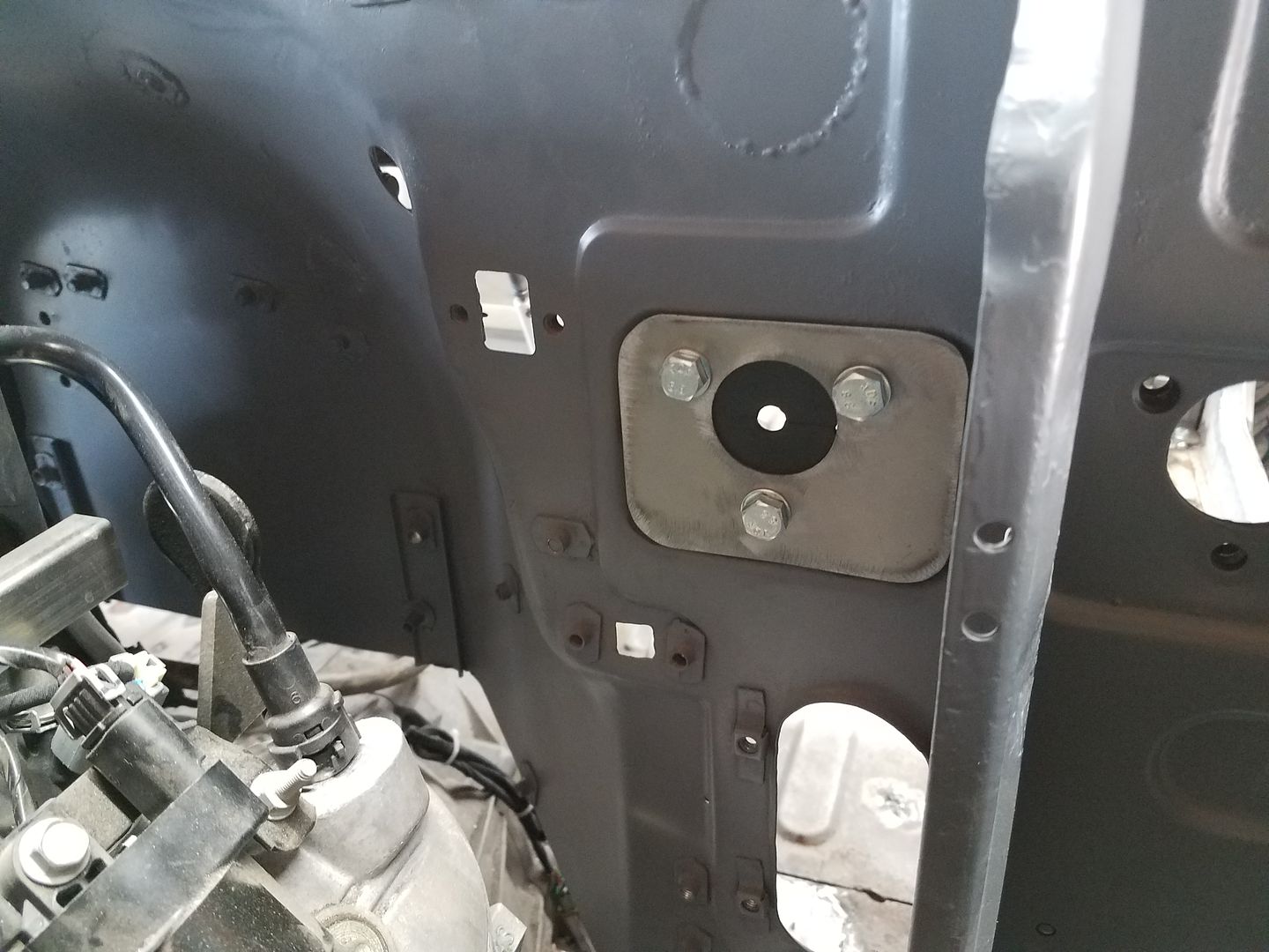
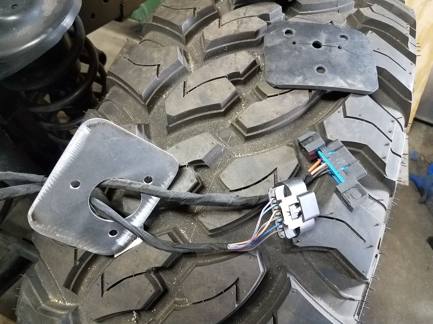
I custom made a pass through grommet for the fit in the old master cylinder mounting hole ( the booster and master are now on the clutch pedal side with a reworked pedal ). The base hole was JUST big enough to pass the OBD2 and DBW pedal through. It was nice to have some threaded holes to work with already in the firewall too. I hate drilling new holes....
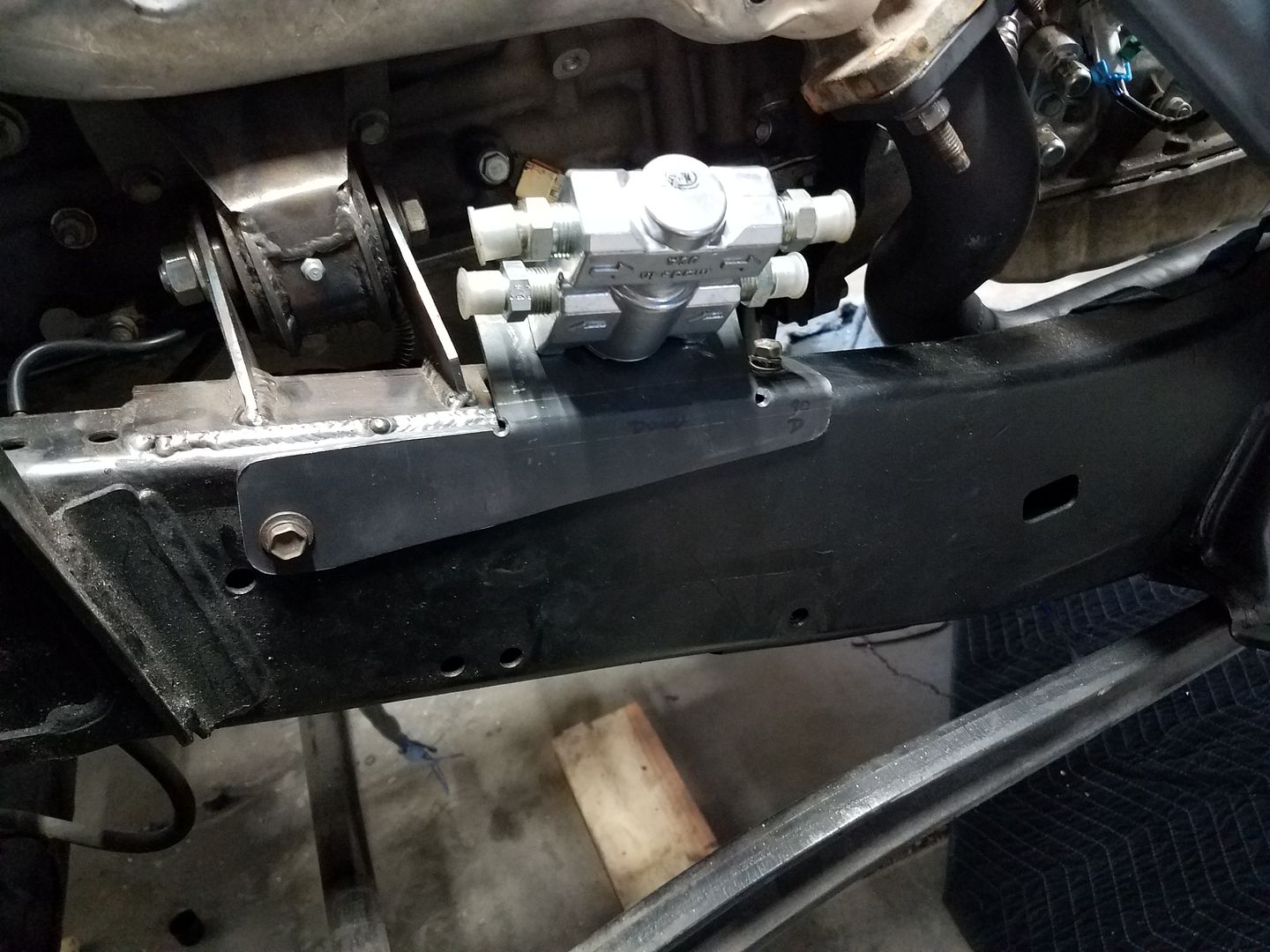
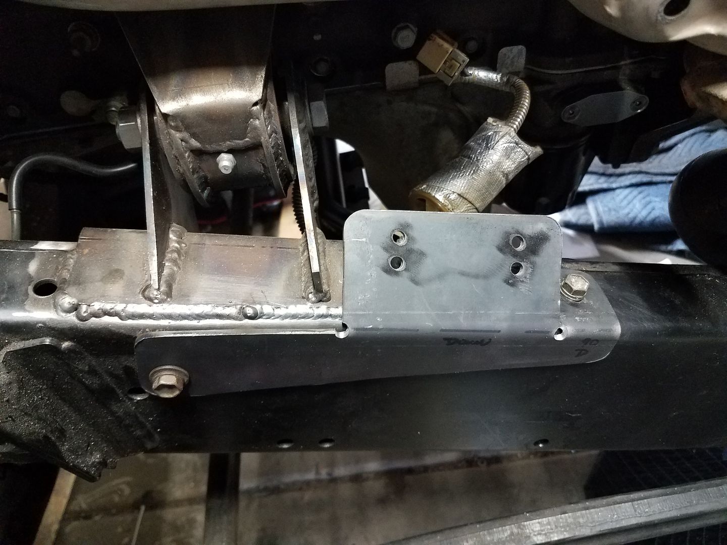
I also made a bracket for the Derale Thermostat housing for the transmission cooler. Again, didn't want to drill a bunch of holes. I also didn't want it mounted to the fender or something. I found a few threaded holes in the frame I wasn't using so I decided to use those.
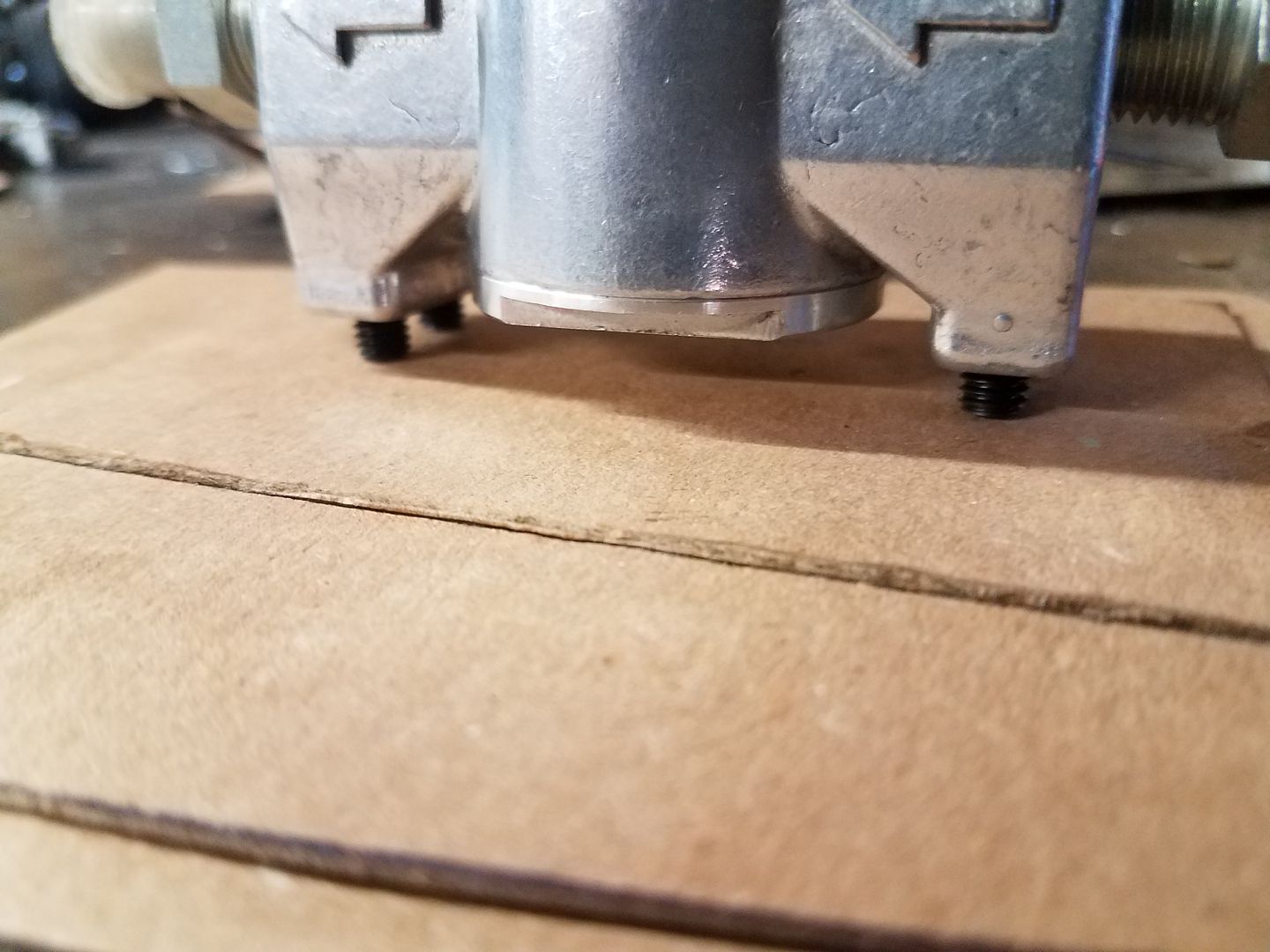
I made a chip board template. The holes from the frame where transferred with a ball peen hammer while the template was held in place with magnets. The hole pattern for the thermostat was transferred with some set screws in the mount holes and some firm pressure to mark the chip board.
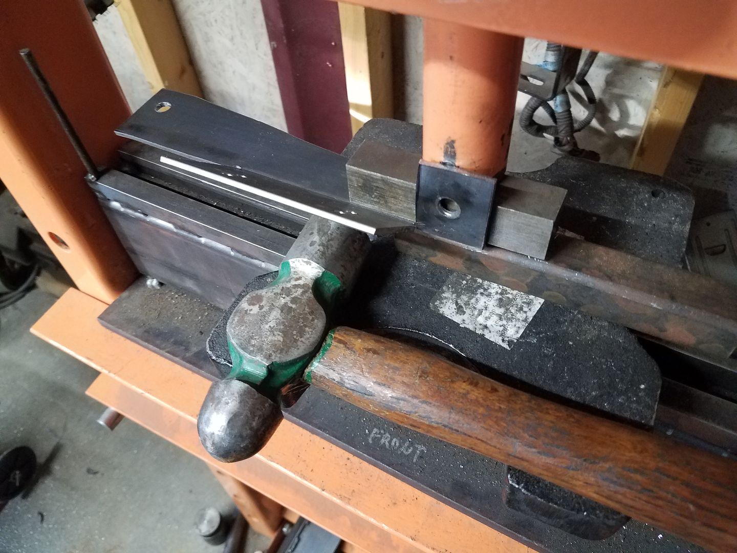
The double bend angle tabs where a little challenging. I didn't want to dig my big press brake out for this little part. I did the shallow bend in my little HF press brake setup to get things started. Then I clamped the part in place with the press and used a hammer to bend the small tab over to the full 90 degrees. The press makes a GREAT clamp with 20 tons of force, which is WAY better than trying to use the edge of a table.
I decided to change the fittings on the thermostat to JIC/AN style so I can use normal hydraulic hose setups. I am lucky enough to be able to get hoses made at my work with crimped ends and just about any fitting I want. I think I can plumb just about everything with -6 through both the transmission and steering systems. That will let me carry a few field fittings and a spare section of line for repairs on the trail I hope.

Re-plumbed the vent tube for the 6L80E transmission up to behind the intake on engine. That is pretty high on this chassis....

Worked on making some hole patch seams disappear....


I custom made a pass through grommet for the fit in the old master cylinder mounting hole ( the booster and master are now on the clutch pedal side with a reworked pedal ). The base hole was JUST big enough to pass the OBD2 and DBW pedal through. It was nice to have some threaded holes to work with already in the firewall too. I hate drilling new holes....


I also made a bracket for the Derale Thermostat housing for the transmission cooler. Again, didn't want to drill a bunch of holes. I also didn't want it mounted to the fender or something. I found a few threaded holes in the frame I wasn't using so I decided to use those.
I made a chip board template. The holes from the frame where transferred with a ball peen hammer while the template was held in place with magnets. The hole pattern for the thermostat was transferred with some set screws in the mount holes and some firm pressure to mark the chip board.
The double bend angle tabs where a little challenging. I didn't want to dig my big press brake out for this little part. I did the shallow bend in my little HF press brake setup to get things started. Then I clamped the part in place with the press and used a hammer to bend the small tab over to the full 90 degrees. The press makes a GREAT clamp with 20 tons of force, which is WAY better than trying to use the edge of a table.
I decided to change the fittings on the thermostat to JIC/AN style so I can use normal hydraulic hose setups. I am lucky enough to be able to get hoses made at my work with crimped ends and just about any fitting I want. I think I can plumb just about everything with -6 through both the transmission and steering systems. That will let me carry a few field fittings and a spare section of line for repairs on the trail I hope.
Metcalf
Expedition Leader
Ok.....holy cow I am behind....kinda busy trying to get this thing together.
Let me try to catch ya up.
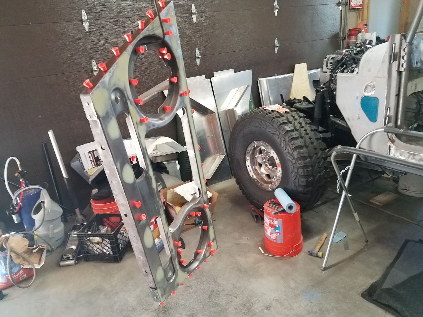
I started on some body work with the grill. It took a few applications of filler, but I got things pretty straight. I tried to use some ear plugs for holes protectors...meh. Small rolls of masking tape work better I think.
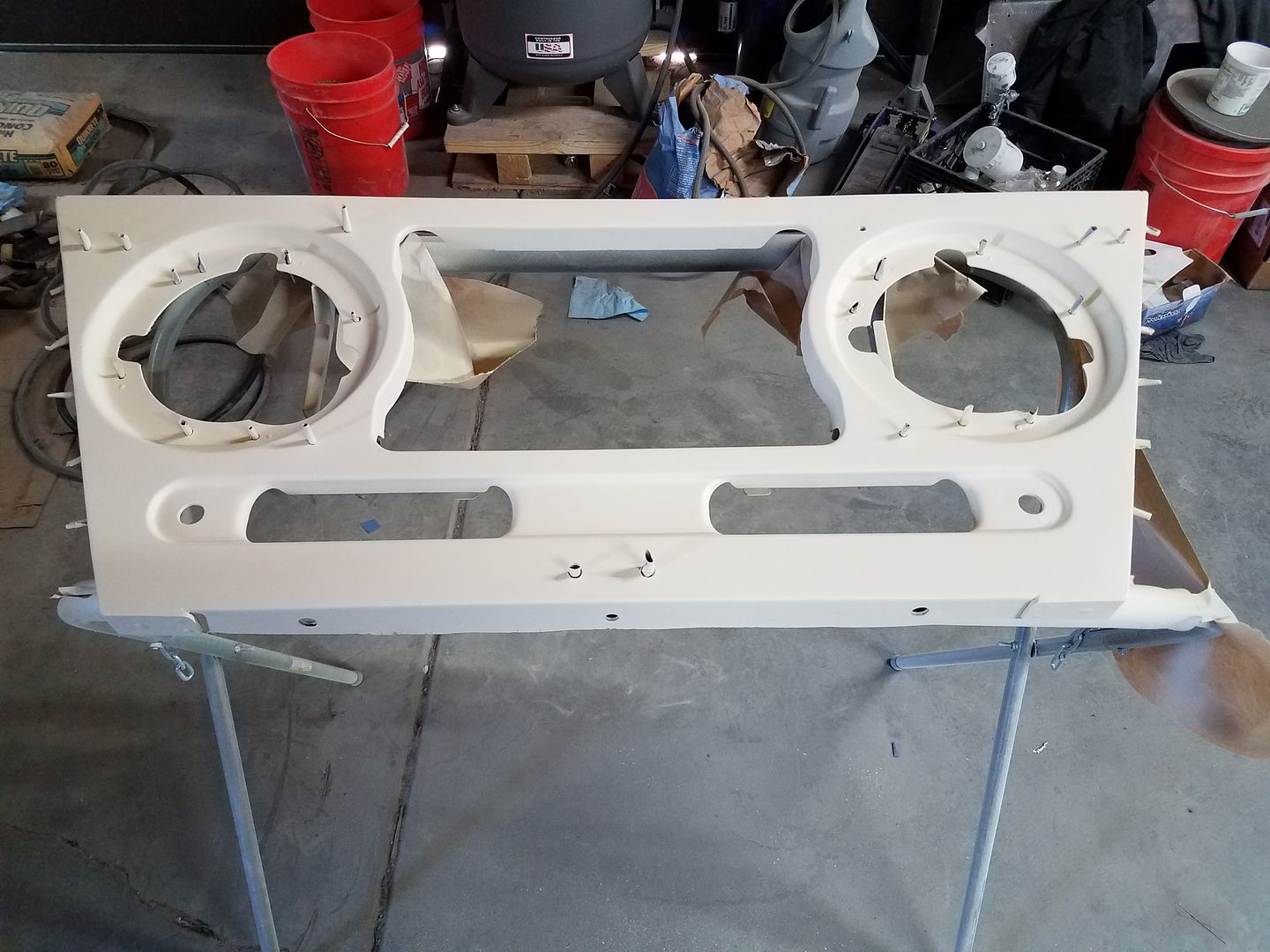
I did epoxy primer on both sides, and then 2 good wet coats of sandable primer down to 320grit. Overall I am pretty happy. It isn't show car perfect, but for a guy in his garage who doesn't really know what he is going, and a part that I cut in to 4 parts, added 4 panels, and did 6 feet of tig welding on.
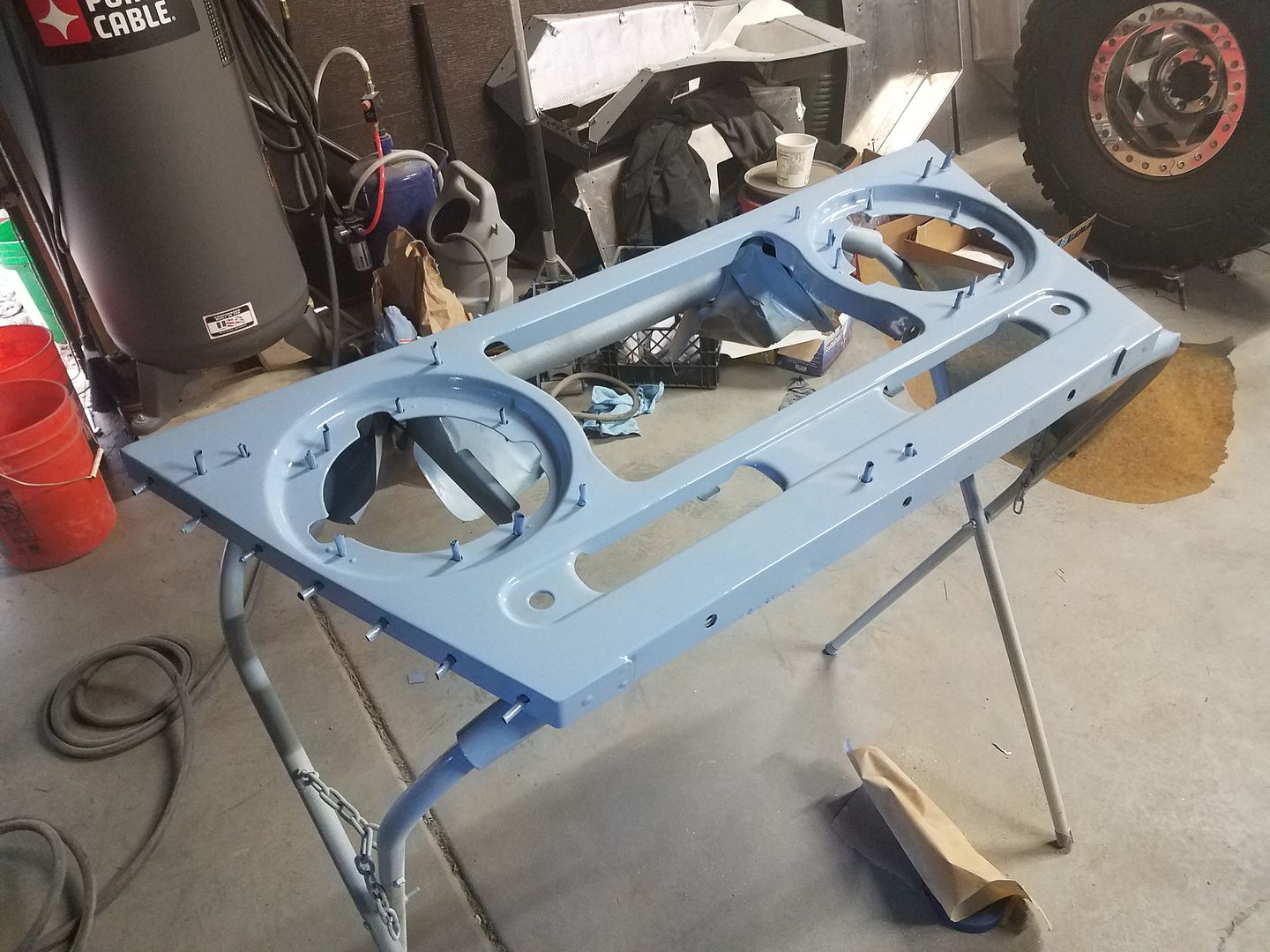
Here is a terrible picture of the first bit of paint. I am using a single stage system that seems to work pretty well. It is a color called Glacier Blue. It is much lighter and brighter in person. I can't wait to get it assembled and out into the light!
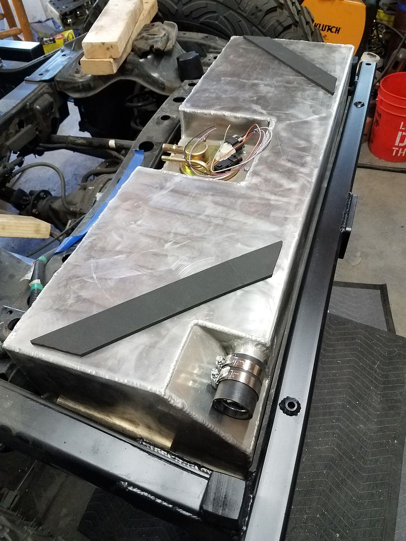
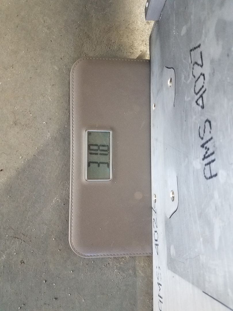
I pulled bed frame for finish welding and a trip to the sand blaster. While it was off I pulled things all apart to paint the rear bumper/crossmember. The gas tank skidplate had to get pulled, and I finally remembered to weight it ( it was 26lbs by the way ). I got to put it all back together for the last time.
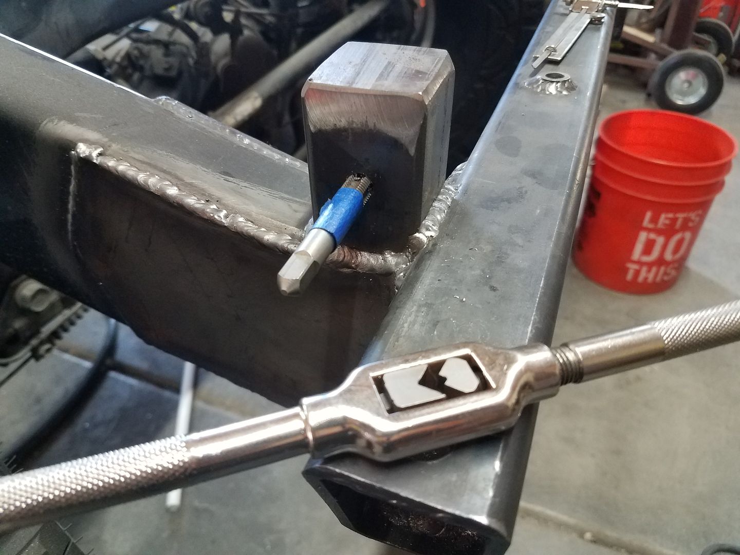
While the frame is off, I needed to drill and tap the bed posts for the mounting hardware. It's metric, because I have OCD issues.
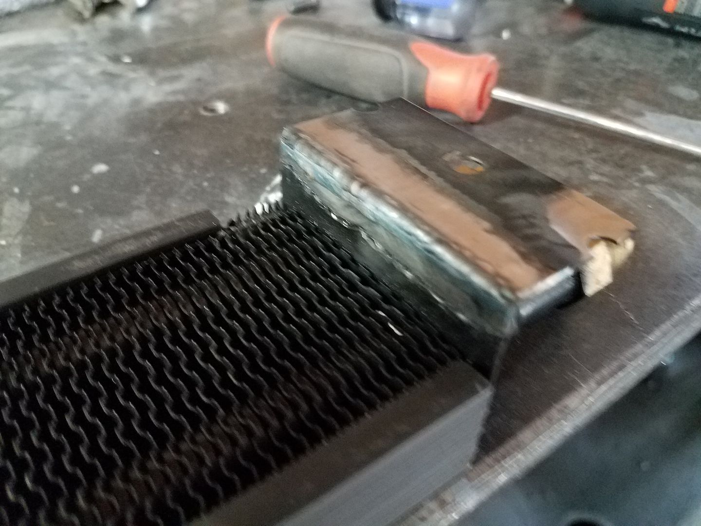
I ended up having to modify the power steering cooler a little bit for some more fitting clearance...ugh. A little tig welding and rattle can black and it was all ok.
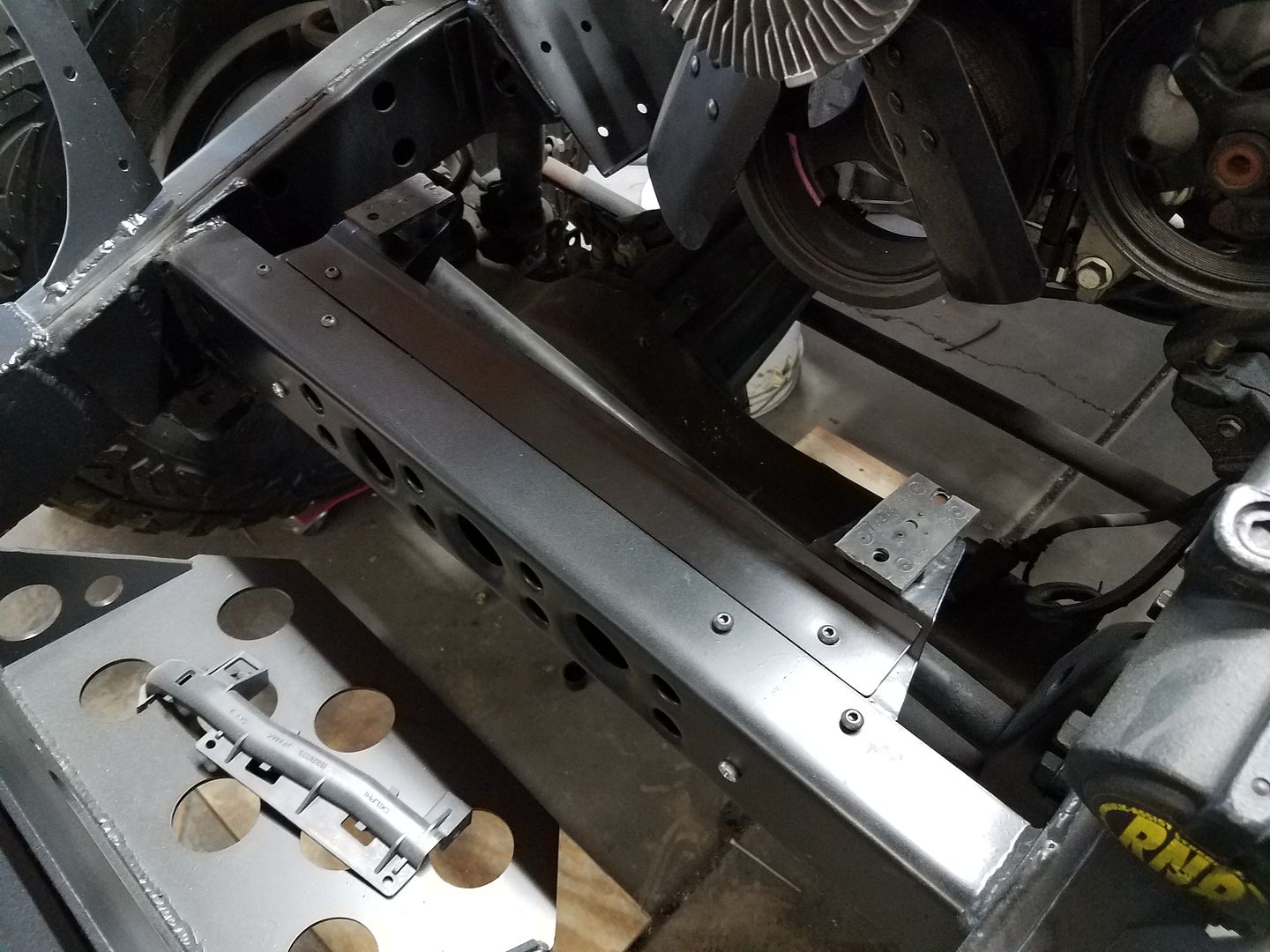
While the paint on the grill was getting nice and hard, I did a little assembly on the front crossmember with the power steering cooler and lower radiator mounts.
Let me try to catch ya up.

I started on some body work with the grill. It took a few applications of filler, but I got things pretty straight. I tried to use some ear plugs for holes protectors...meh. Small rolls of masking tape work better I think.

I did epoxy primer on both sides, and then 2 good wet coats of sandable primer down to 320grit. Overall I am pretty happy. It isn't show car perfect, but for a guy in his garage who doesn't really know what he is going, and a part that I cut in to 4 parts, added 4 panels, and did 6 feet of tig welding on.

Here is a terrible picture of the first bit of paint. I am using a single stage system that seems to work pretty well. It is a color called Glacier Blue. It is much lighter and brighter in person. I can't wait to get it assembled and out into the light!

I pulled bed frame for finish welding and a trip to the sand blaster. While it was off I pulled things all apart to paint the rear bumper/crossmember. The gas tank skidplate had to get pulled, and I finally remembered to weight it ( it was 26lbs by the way ). I got to put it all back together for the last time.

While the frame is off, I needed to drill and tap the bed posts for the mounting hardware. It's metric, because I have OCD issues.

I ended up having to modify the power steering cooler a little bit for some more fitting clearance...ugh. A little tig welding and rattle can black and it was all ok.

While the paint on the grill was getting nice and hard, I did a little assembly on the front crossmember with the power steering cooler and lower radiator mounts.
Metcalf
Expedition Leader
......one more.....Time for more body work!
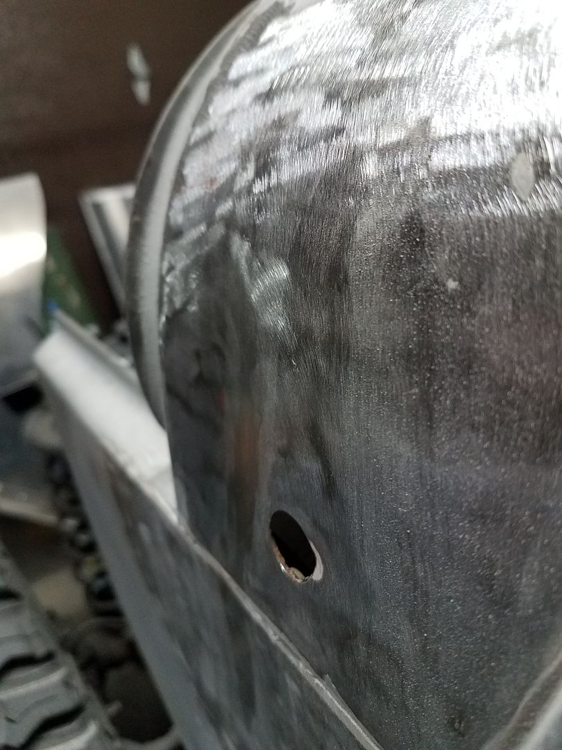
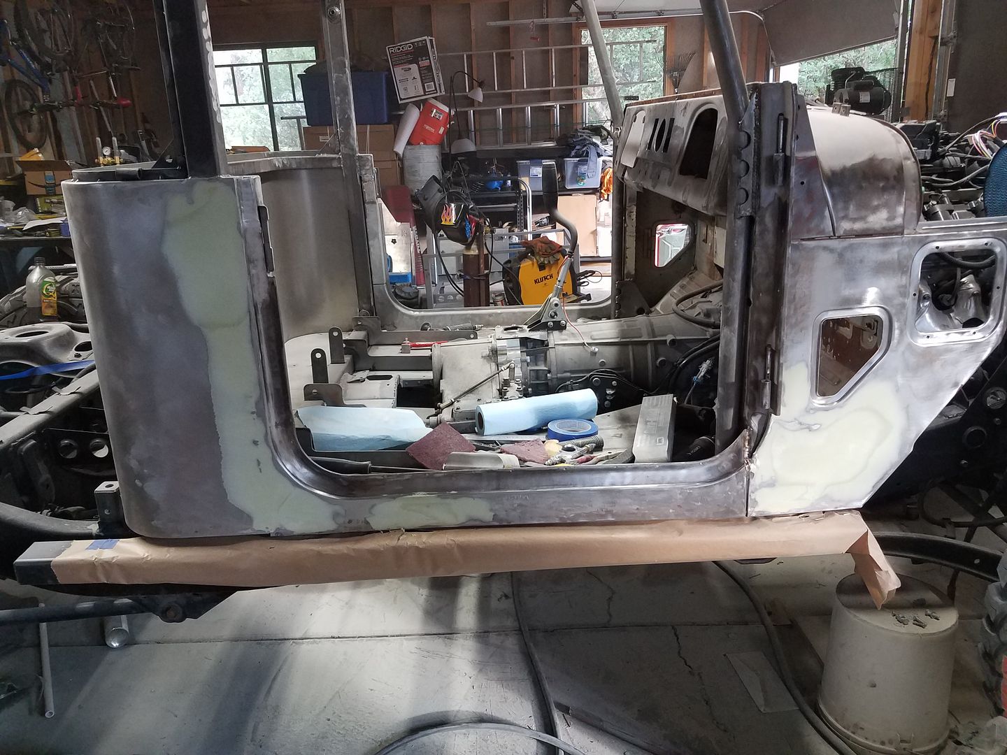
I found this surprise under about 3/8 of an inch of bad body filler on the drivers side cowl. Super fun.
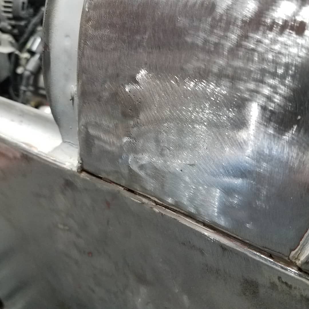
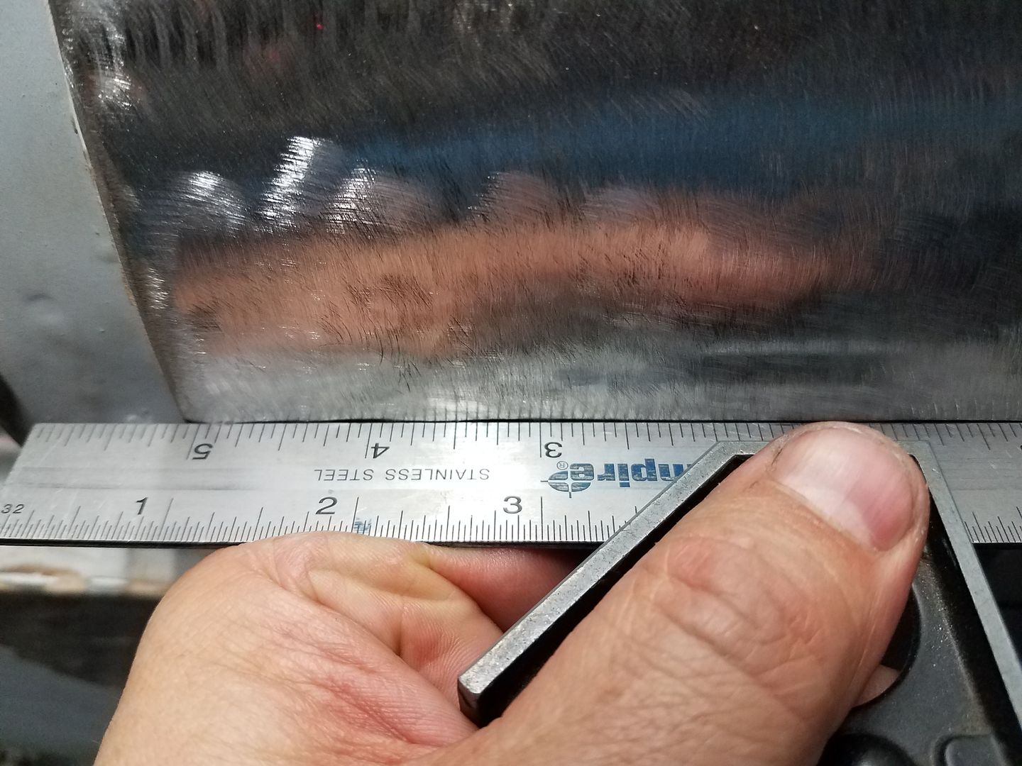
After much love from some body hammers, some hot and cold shrinking, a tig welded hole patch, and some patience it mostly disappeared. I was able to go from 3/8 an inch of dent to a wavy 1/16 over the entire panel. I'd not going for show car, but I have to try....
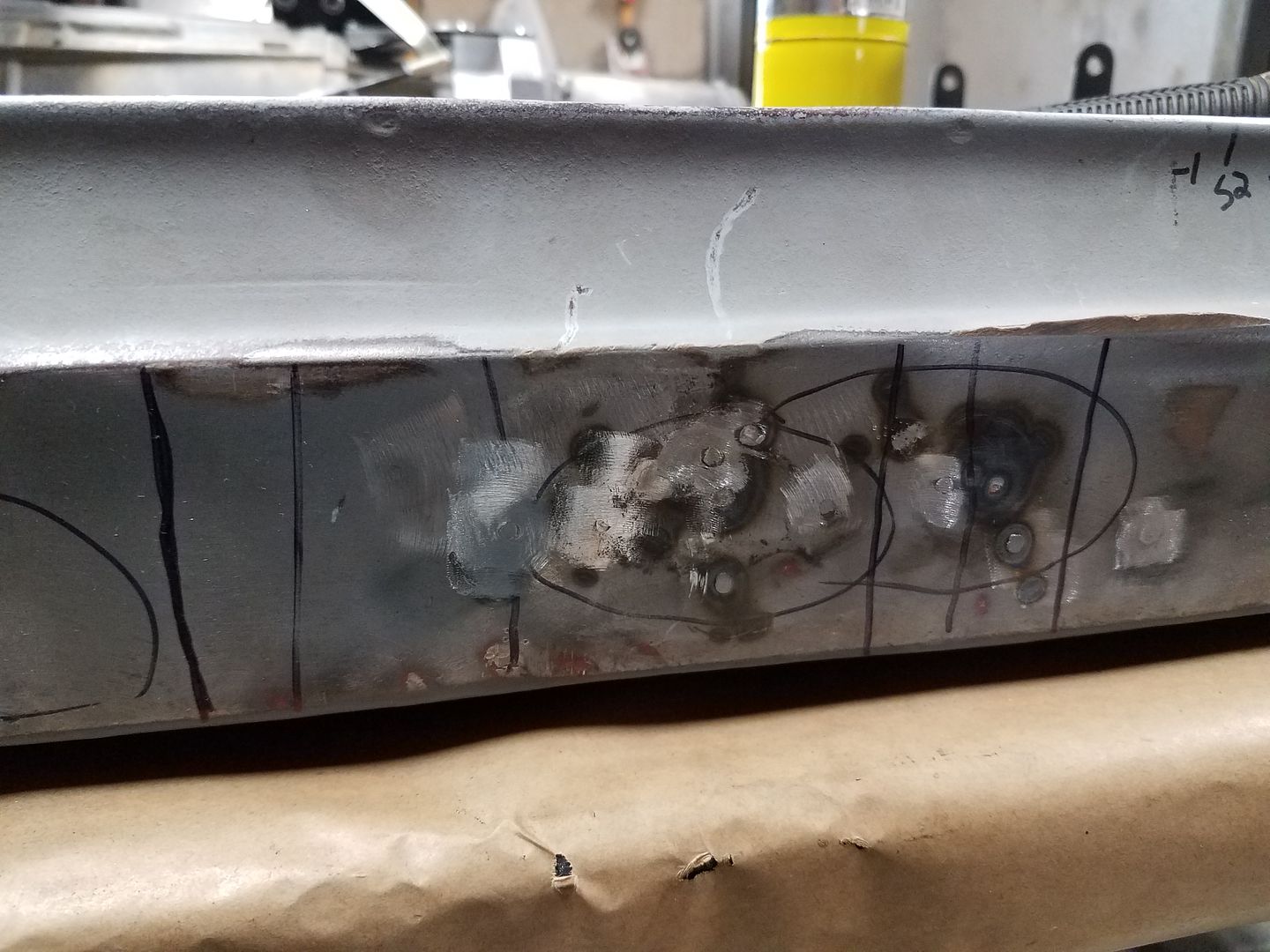
The rocker panel also had a few surprises on both sides. The tub is almost 50 years old and I got it for a few hundred bucks. Somewhere in there my stud welder from HF showed up. That sure was handy for fixing things on the double wall rocker section!
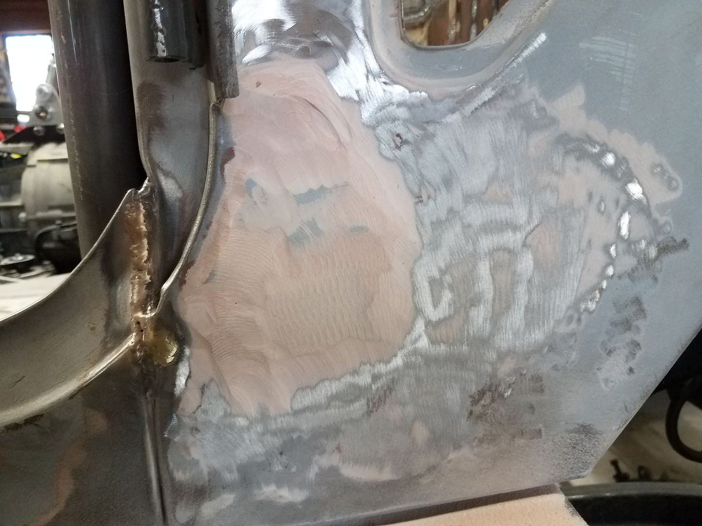
Just when I thought things where going my way, I got this lump of coal in my stocking on the passenger side. Ouch. It was the size of a small dinner plate and about 3/8" thick!
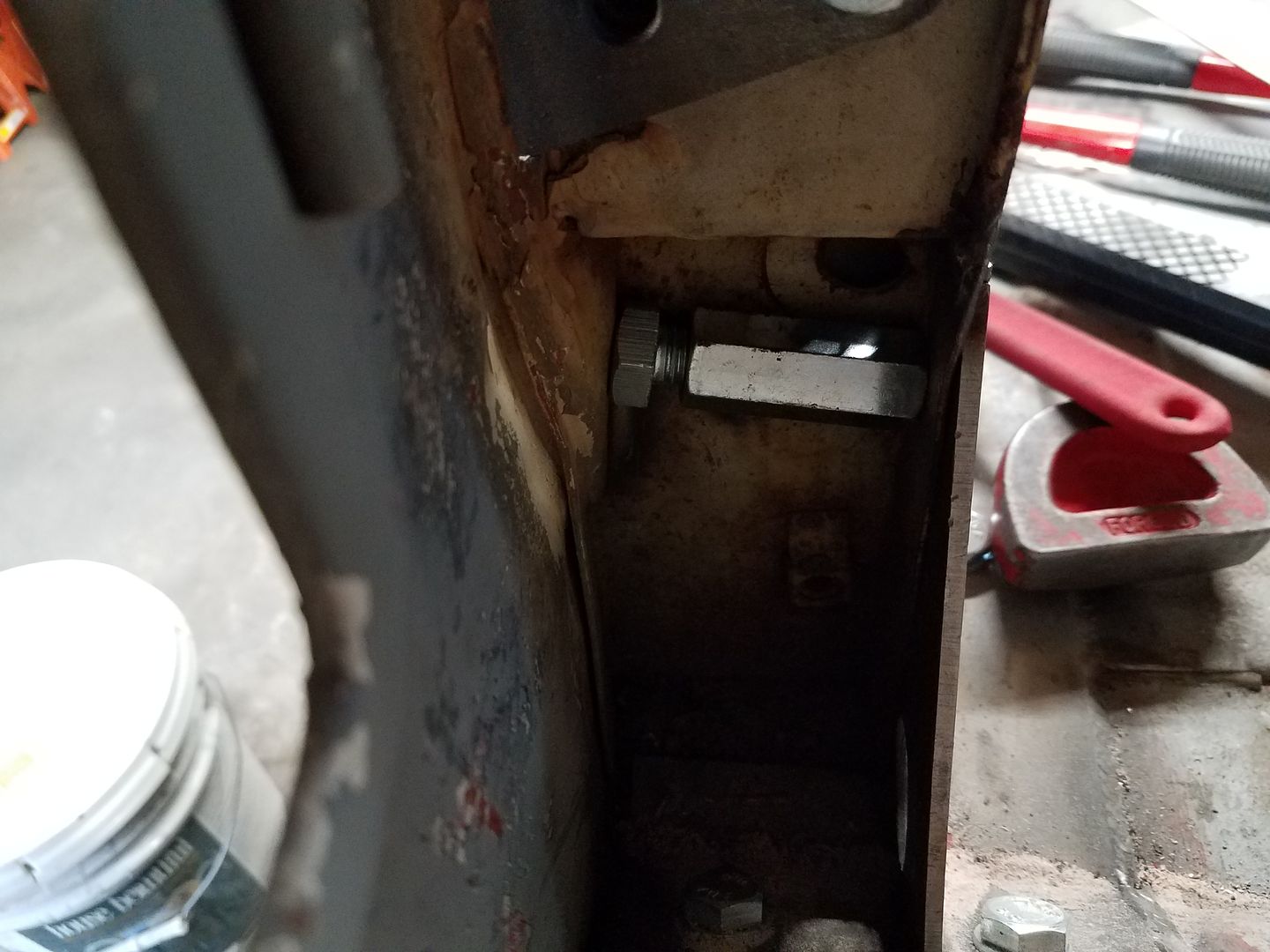
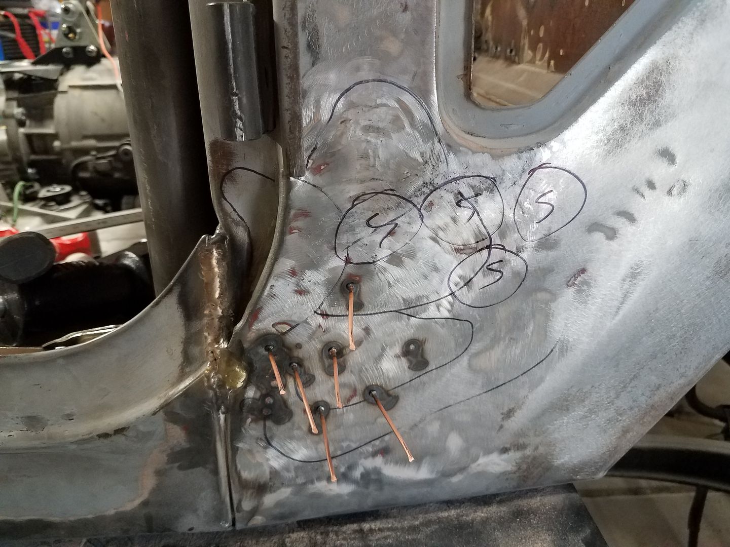
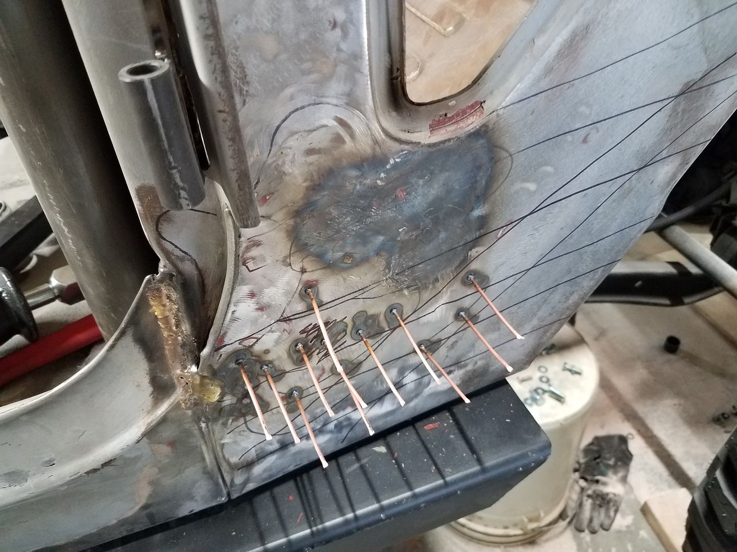
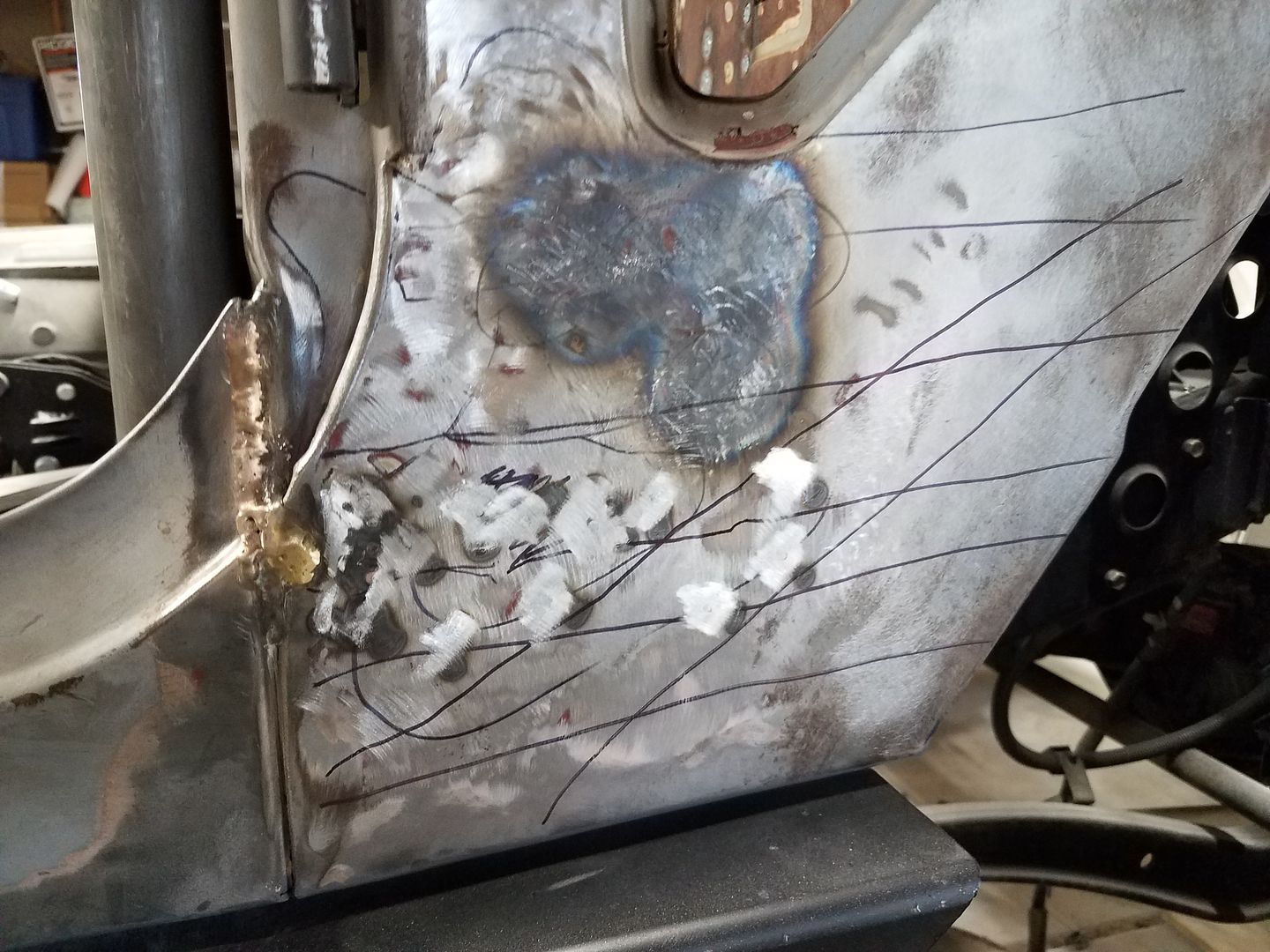
After turning into a porcupine with the stud welder, hitting it with a hammer, making a home made jack screw, and doing some heat/cold shrinking it finally started to look half way decent again. A lot of stuff was smooshed that I couldn't really get to in double wall sections and stuff. I think the worst place is about 1/8, but overall it is better than 1/16 which is fine for a skim coat of filler rather the lump it had before!
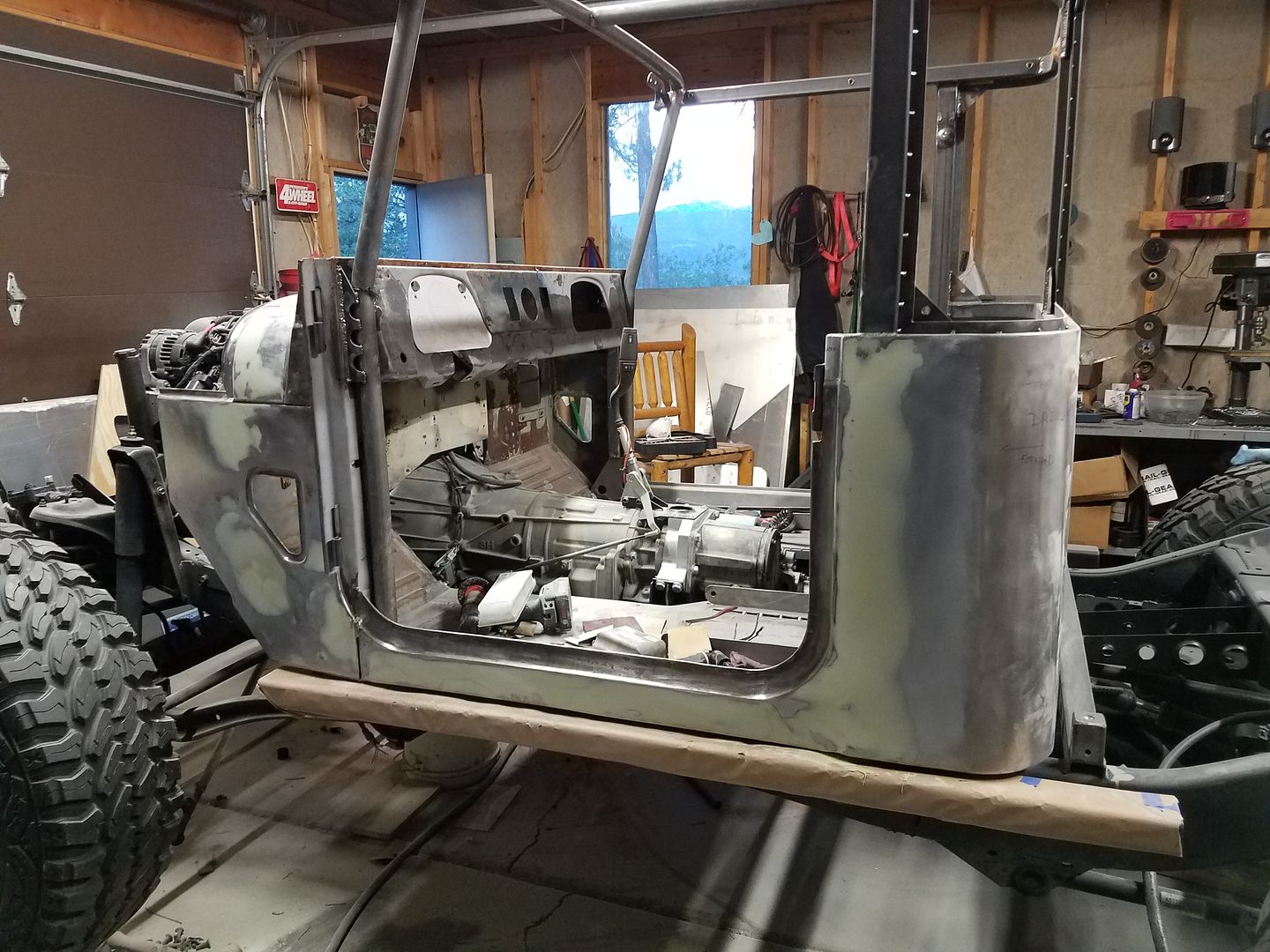
I skipped over a few steps, but this is where I am at as of tonight. The drivers side is all skimmed and sanded in filler. Now onto the passenger side, then a bit of work on the dash panel, and hopefully some primer by late this weekend!

I found this surprise under about 3/8 of an inch of bad body filler on the drivers side cowl. Super fun.


After much love from some body hammers, some hot and cold shrinking, a tig welded hole patch, and some patience it mostly disappeared. I was able to go from 3/8 an inch of dent to a wavy 1/16 over the entire panel. I'd not going for show car, but I have to try....

The rocker panel also had a few surprises on both sides. The tub is almost 50 years old and I got it for a few hundred bucks. Somewhere in there my stud welder from HF showed up. That sure was handy for fixing things on the double wall rocker section!

Just when I thought things where going my way, I got this lump of coal in my stocking on the passenger side. Ouch. It was the size of a small dinner plate and about 3/8" thick!


After turning into a porcupine with the stud welder, hitting it with a hammer, making a home made jack screw, and doing some heat/cold shrinking it finally started to look half way decent again. A lot of stuff was smooshed that I couldn't really get to in double wall sections and stuff. I think the worst place is about 1/8, but overall it is better than 1/16 which is fine for a skim coat of filler rather the lump it had before!

I skipped over a few steps, but this is where I am at as of tonight. The drivers side is all skimmed and sanded in filler. Now onto the passenger side, then a bit of work on the dash panel, and hopefully some primer by late this weekend!
changingground
Member
Keep on grinding away. I appreciate your dedication to sharing even some of the story with us.
Metcalf
Expedition Leader
Metcalf
Expedition Leader
Holy Carp I am behind! Things are accelerating as I push towards my September completion date. If you want daily updates please look me up on facebook or instagram....brennanmetcalf.
http://s125.photobucket.com/user/Metcalfphoto/media/Blender/20180730_170437_zpsceh0ea4b.jpg.html]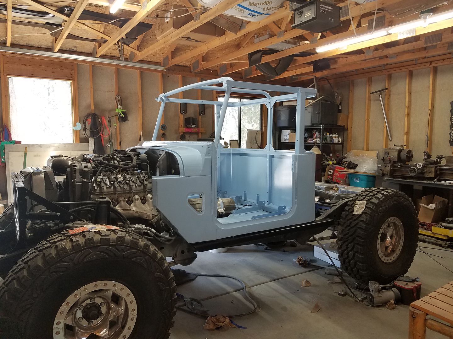 [/URL]
This is where I am at today. I got the tub painted this weekend. Oh boy is it blue!
I have been working on a lot of other things as I progressed to paint...
-Transmission cooler lines are made and mounted along with the transmission thermostat.
-The power steering lines are all done. This included the low pressure return lines along with the pressure lines and assist ram lines.
-I have most of a power steering reservoir extension made.
-Coolant overflow bottle started
-I had to fix a few issues with the new HD drag link
-The cooling system is mostly plumbed other than the heater
-Suck down winch installed
The paint process was...
-Epoxy DTM primer, two wet coats inside and out.
-Sanded with 320
-Primer Surfacer, two wet coats outside and on the 'cage'
-Sanded with 320
-A bit of glaze
-Sanded with 320
-Another coat of Primer Surfacer
-Sanded with 320
-PAINT! lots of blue paint. I am using a single stage from TCP Global.
Lots done....Lots to do.
http://s125.photobucket.com/user/Metcalfphoto/media/Blender/20180719_173751_zpszvapq8fl.jpg.html]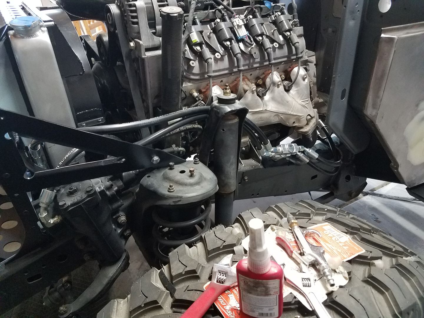 [/URL]
http://s125.photobucket.com/user/Metcalfphoto/media/Blender/20180719_173746_zps6nwacrnn.jpg.html]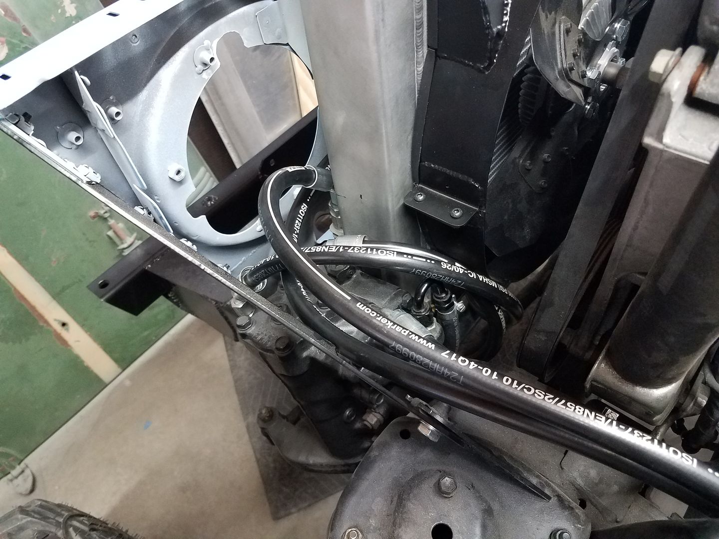 [/URL]
http://s125.photobucket.com/user/Metcalfphoto/media/Blender/20180719_173756_zpskzgeuzgl.jpg.html]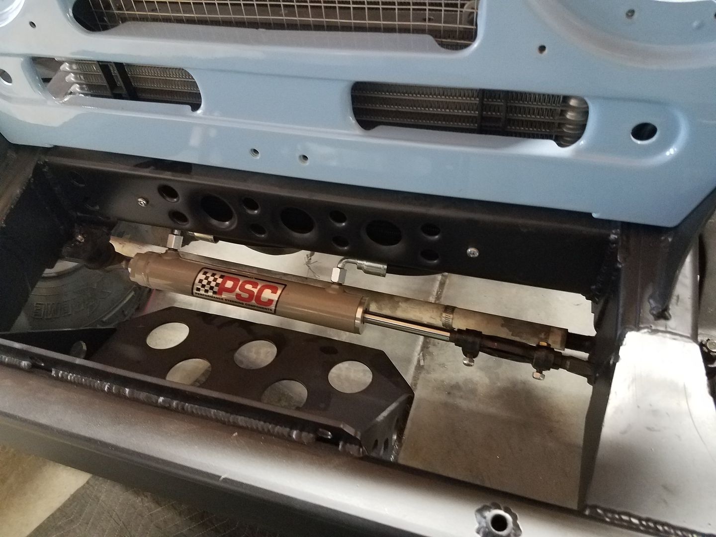 [/URL]
http://s125.photobucket.com/user/Metcalfphoto/media/Blender/20180717_185650_zps4uiwhstf.jpg.html]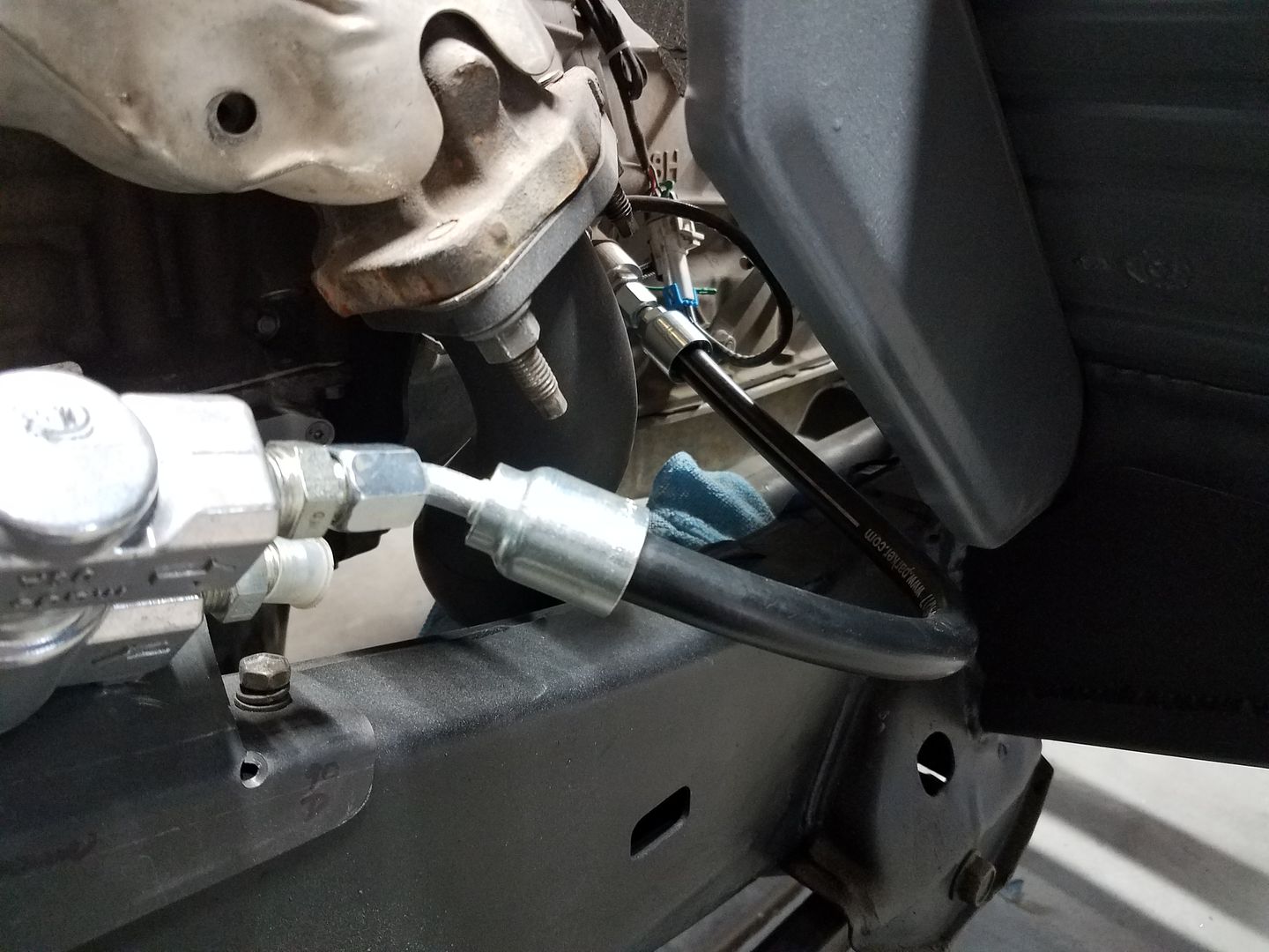 [/URL]
http://s125.photobucket.com/user/Metcalfphoto/media/Blender/20180717_182330_zpsr9cteekz.jpg.html]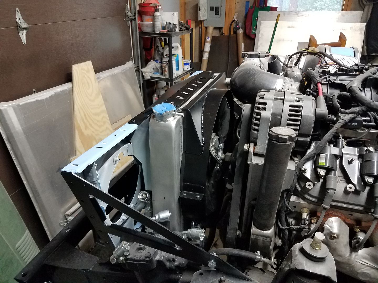 [/URL]
http://s125.photobucket.com/user/Metcalfphoto/media/Blender/20180717_172015_zpsrpexfx8j.jpg.html]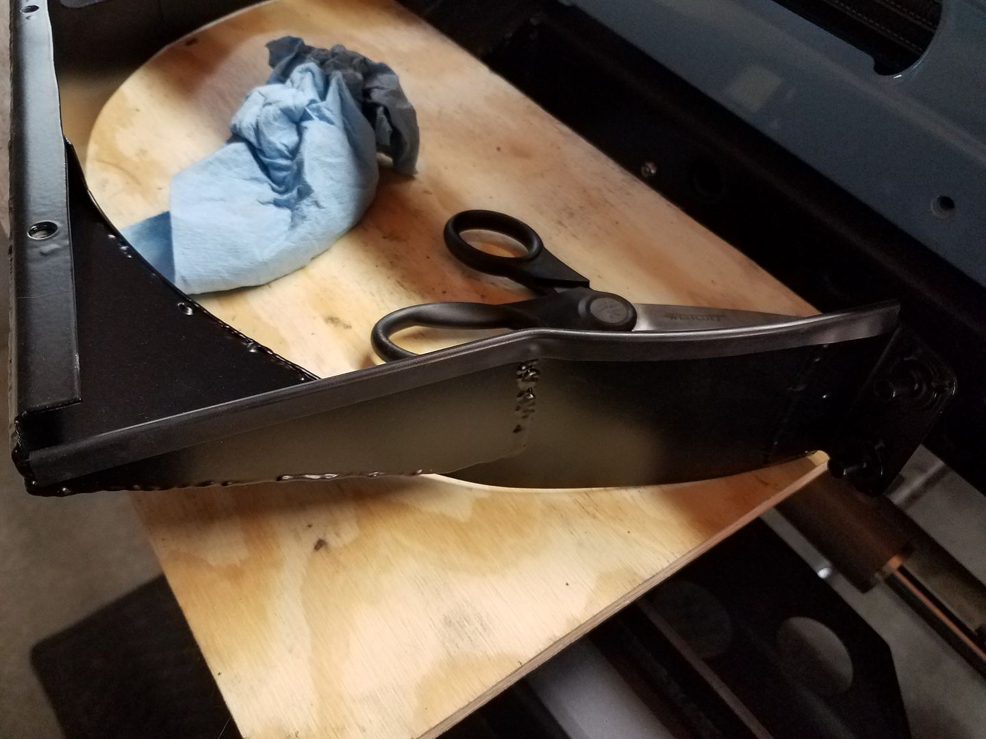 [/URL]
http://s125.photobucket.com/user/Metcalfphoto/media/Blender/IMG_20180715_170659_880_zpsy19vxwlg.jpg.html]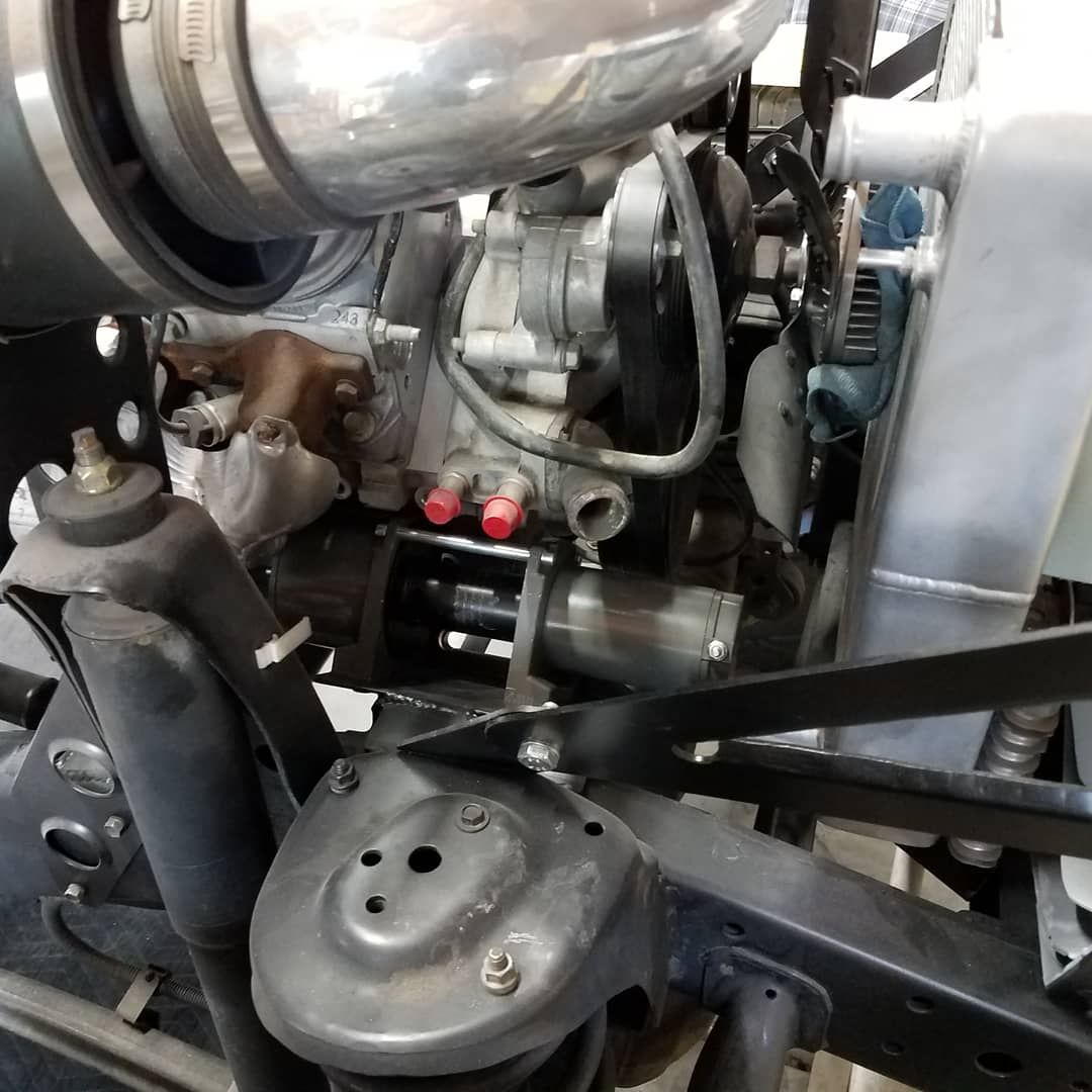 [/URL]
http://s125.photobucket.com/user/Metcalfphoto/media/Blender/20180713_174900_zpsdi96v3n1.jpg.html]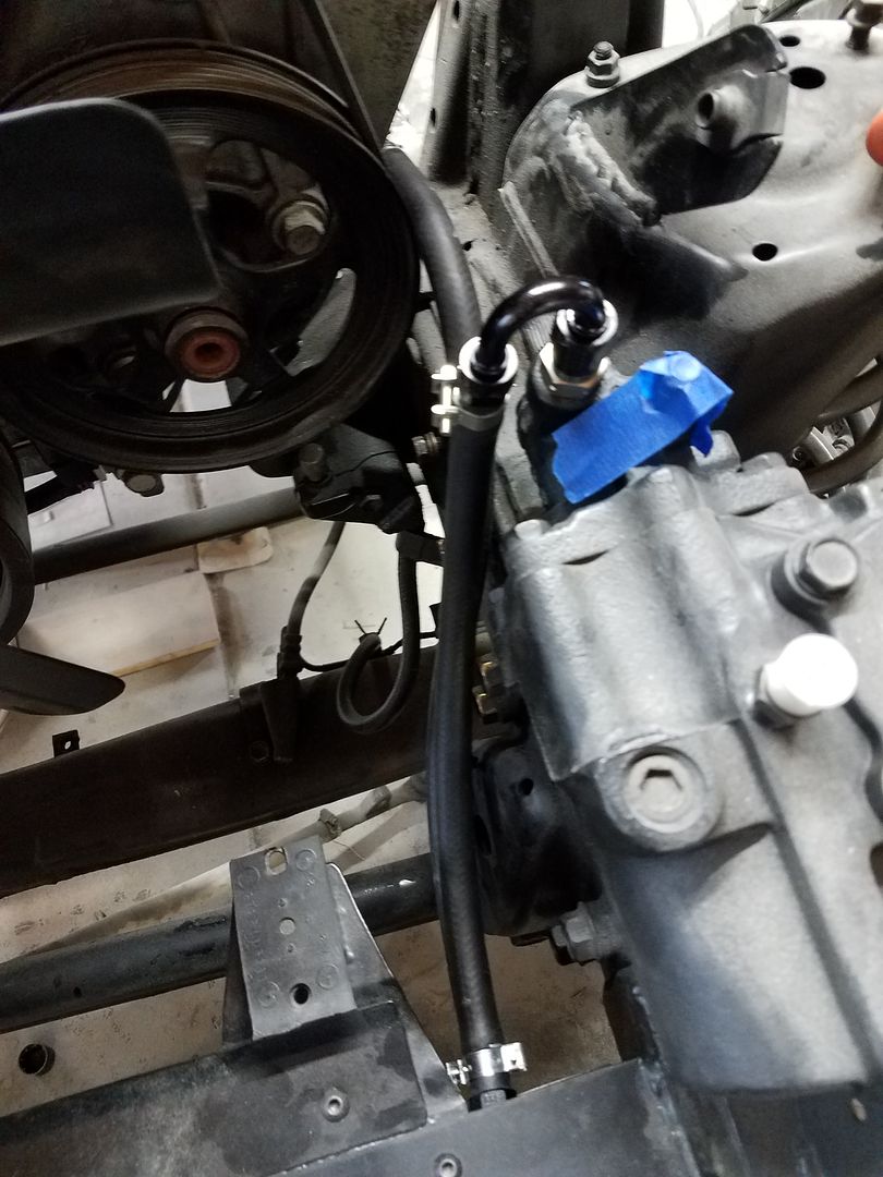 [/URL]
http://s125.photobucket.com/user/Metcalfphoto/media/Blender/IMG_20180728_102806_832_zpsh32ogreq.jpg.html]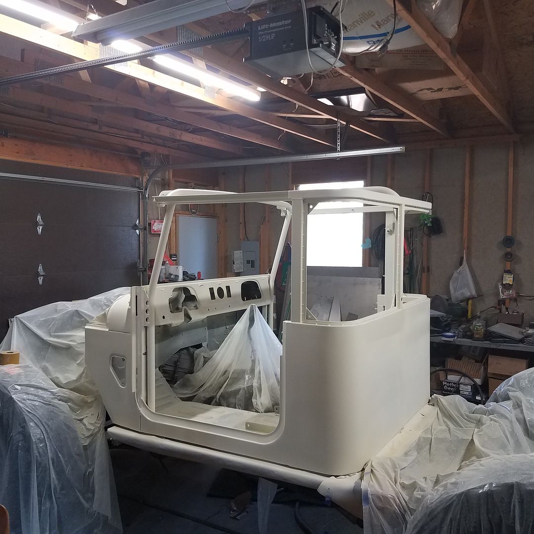 [/URL]
http://s125.photobucket.com/user/Metcalfphoto/media/Blender/20180730_170437_zpsceh0ea4b.jpg.html]
 [/URL]
This is where I am at today. I got the tub painted this weekend. Oh boy is it blue!
I have been working on a lot of other things as I progressed to paint...
-Transmission cooler lines are made and mounted along with the transmission thermostat.
-The power steering lines are all done. This included the low pressure return lines along with the pressure lines and assist ram lines.
-I have most of a power steering reservoir extension made.
-Coolant overflow bottle started
-I had to fix a few issues with the new HD drag link
-The cooling system is mostly plumbed other than the heater
-Suck down winch installed
The paint process was...
-Epoxy DTM primer, two wet coats inside and out.
-Sanded with 320
-Primer Surfacer, two wet coats outside and on the 'cage'
-Sanded with 320
-A bit of glaze
-Sanded with 320
-Another coat of Primer Surfacer
-Sanded with 320
-PAINT! lots of blue paint. I am using a single stage from TCP Global.
Lots done....Lots to do.
http://s125.photobucket.com/user/Metcalfphoto/media/Blender/20180719_173751_zpszvapq8fl.jpg.html]
 [/URL]
http://s125.photobucket.com/user/Metcalfphoto/media/Blender/20180719_173746_zps6nwacrnn.jpg.html]
 [/URL]
http://s125.photobucket.com/user/Metcalfphoto/media/Blender/20180719_173756_zpskzgeuzgl.jpg.html]
 [/URL]
http://s125.photobucket.com/user/Metcalfphoto/media/Blender/20180717_185650_zps4uiwhstf.jpg.html]
 [/URL]
http://s125.photobucket.com/user/Metcalfphoto/media/Blender/20180717_182330_zpsr9cteekz.jpg.html]
 [/URL]
http://s125.photobucket.com/user/Metcalfphoto/media/Blender/20180717_172015_zpsrpexfx8j.jpg.html]
 [/URL]
http://s125.photobucket.com/user/Metcalfphoto/media/Blender/IMG_20180715_170659_880_zpsy19vxwlg.jpg.html]
 [/URL]
http://s125.photobucket.com/user/Metcalfphoto/media/Blender/20180713_174900_zpsdi96v3n1.jpg.html]
 [/URL]
http://s125.photobucket.com/user/Metcalfphoto/media/Blender/IMG_20180728_102806_832_zpsh32ogreq.jpg.html]
 [/URL]
elephant man
New member
Awesome work, as usual.
Similar threads
- Replies
- 6
- Views
- 956
- Replies
- 8
- Views
- 918
- Replies
- 12
- Views
- 4K
- Replies
- 2
- Views
- 3K

