How to make a cheap isolated dual-battery setup for $50

dwh

Tail-End Charlie
-- The cable between the starter batteries and the camper batteries causes the battery bank with a lower voltage to draw down the other. This is the classic set up of all relay controlled dual battery systems. The trick is that rather than a small wire, I have a properly sized cable, so the camper batteries are able to draw down the starter batteries very quickly and thus recharge very quickly.

There's that (possibly) dodgy assumption again. See below.


all of the logic that I am using is covered on the Smart Gauge site

I referred to this a few posts back, but I'ma gonna do 'er agin.

http://www.smartgauge.co.uk/nosurge2.html


Where he says:

"We're not quite finished yet. The proponents of this false rumour usually state "one full battery and one flat battery" so that is the example I based the above on. They are obviously unaware that this state of charge does not cause the greatest current to flow.

The worst scenario actually occurs with a fully charged engine start battery and the auxiliary battery bank at around 40% charge state. The reason is that, although the terminal voltage falls as the battery approaches totally flat, the internal resistance rises. At 40% state of charge the internal resistance is considerably lower. The result in the above example would be that the initial current surge would be around 40 amps, and even that would only last a minute or so (thus discharging the engine battery by 40A * 1/60th hour = 0.7 amp hours) at the most until the surface charge on the auxiliary bank raised it's terminal voltage to that of the engine start battery. Once this had happened, the current would be negligible." [emphasis added - dwh]


Now, he's talking about connecting two batteries using a solenoid (SmartBank setup) but he's also NOT factoring in a running alternator. In your rig, by the time the the IBS ties the batteries, the alternator is up and running and so the current surge between main and aux banks would be even LESS than what he shows here in this example. Also, he's using 40% SoC in the example, but I see you say that your aux bank is usually around 75% SoC - so the surge would be even more less (parse that!)
 

dwh

Tail-End Charlie
I wasn't asking about measuring voltage at the starter battery, but about measuring amp flow from the starter battery to the aux battery.

It's that idea of a big surge from the starter battery to the aux battery when the IBS ties them that I question (and SmartGauge denies).


Most dual battery setups wired with #10 wire? Wait...what?

That'd be a new one on me. Most I've seen were done with standard off the shelf battery cables.

I did recommend someone with a CTEK 250s use #10, but that's a 20a DC-DC charger, not a split-charge relay.


Yea, I was wondering about that 15.5v and the Lifelines myself. What does Lifeline have to say about it?
 

wrcsixeight

Adventurer
I wish I had a enough data to make a graph of what my single depleted group 31 takes from the alternator. I do not take power from starting battery but right from alternator (+) stud. Alternator (+) through circuit breaker to Ignition Stud on Manual battery switch, from there I choose which battery is feeding the starter or being fed by the alternator.

I can tell you when I turn my manual switch, allowing the flooded group 31 to feed on the alternator current, the amps flowing into the 31 will be in the 50 to 65 amp range if you want to call that a surge, and many miles later will still be taking 40 amps.

I can easily see 5 Lifelines sucking a constant 150 amps. I notice my Northstar AGM gobbles up even more alternator juice than the flooded does, pretty much maxing it out at any given rpm for a surprising timespan. I notice that this AGM when charged by a 25 amps schumacher, does not drop below 20 amps until it is in the 90% SOC range, where as the larger flooded 31 tapers earlier, even when it is rated at 40 more amp hours than the NS AGM.

My vehicular charging system issue is the hot alternator cannot keep up with depleted battery cravings below 1500 rpm, and my voltage regulator decides 14.9v had been allowed for long enough(prematurely), and then says 13.7v is all you get and then charge rate slows to a crawl.

But fatter wire, in my case the direct alternator battery switch feed, and removing the starting battery from the alternator circuit, allows 14.9v and entices that significantly higher amp flow required to hold 14.9v, to stay around for longer.

Wonder how taking power right from the alternator on your system would affect amp flow, Diplostrat.

But why fix what ain't broke. 150 amps is nothing to sneeze at.
 

dwh

Tail-End Charlie
Surges? I have never seen them. What I have seen, have measured, both with a hand held ammeter and with the monitors on the camper battery bank, is a sustained charge rate of over 150A.


I feel like I'm not getting my point across.

You have repeatedly stated that after the IBS ties the batteries, you see a large charging current *from the engine start bank to the house bank*.

That does not jibe with SmartGauge's description of what happens.

Nor does it jibe with what happens in my truck with a dumb ignition switched solenoid.

Nor does it jibe with what I see when I try to picture it. What I see when I picture it, is that the large current flow you are seeing, is coming from the alternator, not the engine bank.


So the question I'm trying to get clear in my mind is:

Have you confirmed that the large current flow after the IBS ties the batteries, is actually coming from the engine bank?
Or, have you measured what is going into the house bank, but not exactly WHAT is supplying the current (house (strike that - and why isn't strikethrough code working?) engine bank or alternator)?

<confusion...>


OOH that reminds me of a good one! Sunday morning dance!!


With a modern alternator/regulator, running at over 14v, there is no longer any reason for this.

If, on the other hand, you have an older vehicle, running at 13v,


Here's another one of those false assumptions.

My truck is a 1976 Ford. 460 engine, bone stock 100a alternator. Bone stock external voltage regulator. I've never changed the voltage regulator, and the truck was sitting for 15 years non-op when I bought it, so there's actually a very good chance that the voltage regulator is the original factory part.

At low idle, the bus voltage on my truck sits at 13.5v. At any RPM above low idle, the bus voltage rises to 14.3v and sits there. (Well technically, it drifts between 14.28v and 14.31v.)

My 1969 Lincoln Continental did the same thing.

My mom had an 84 Dodge van, and for years, she would forget and leave the lights on about once a month and have AAA jump it the next day. After a AAA jump-start guy tried to upsell her a new battery, she told him she'd have "her son the electrician" check it out. After that, every time she'd kill the battery, I wouldn't get a moment's peace until I went over to her house and put on a dog and pony show "checking it out". At speed, that bus would ride rock steady at 14.44v. It did that with a battery that had been totally dead 12 hours before, and it did that after she finally toasted the battery and I replaced it with a new Diehard.

I've owned over 40 cars trucks and vans, and while I didn't test them all, I can't recall offhand ANY that topped out under 14v. Hell, IIRC even the '67 Beetle with a generator ran up around 14.5v.


So I dunno where this rumor came from that "older vehicles don't produce enough voltage"...but I ain't buying it. A few? Sure. Most? Nah.
 
Last edited:

dwh

Tail-End Charlie


So, when the partially discharged camper batteries connect to the fully charged starter batteries, current flows from the charged battery to the discharged battery. If the engine is running, the alternators respond very quickly[...][trimmed down to basics - dwh]

So, after a few seconds, the current is coming from the alternators. I think this is what you are saying, and I agree. [...]


As you have correctly pointed out, they give current when their voltage is higher than that of the bus and they take current when it is lower. At the moment the camper battery connects, it will demand current. That current will come from the starter battery. For how long? I would guess less than about 15 seconds as the alternator will ramp up fairly quickly.[...]

Now see, what I'm thinking is that the alternator is already energized (since it was already supplying amps to the engine bank before the IBS tied in the house bank - in other words, "already ramped up" (which really only takes about .0000001 seconds anyway)), and also that the voltage regulator/alternator (magnetic fields) responds instantly, whereas the engine battery (chemistry) doesn't (ref: Smartgauge surge math).

Also, the alternator is pushing (voltage, i.e., electromotive force, i.e., pressure) against the bus with a stronger force (higher potential) than the engine bank.

Thus the alternator is force-feeding amps down the throat of the engine bank - so when the house bank is tied in, the engine bank is UNABLE to respond because it cannot regurgitate amps back into the bus while the alternator is force-feeding it.

Which means: That big flow of power from the engine bank to the house bank never happens. Looks like a false assumption.

Which is why I was wondering if it had ever actually been measured to see if it really does happen.


[A decent little amp surge *does* happen with my truck with an evldave dumb solenoid isolator setup (the proper name for that BTW ladies and gentlemen is a "split-charge relay"), because that ties the batteries *before* cranking the engine and starting it. Ain't much of a surge, but it's measurable.]


Are we still agreeing

Not yet, but you're catching on. :ylsmoke:

(Woulda been a lot easier if we were on the job site - I coulda just rapped you on the hardhat with my Klein's till you got it. :littlefriend:
Trying to do it "diplomatically" takes a bit longer. :D )
 

dwh

Tail-End Charlie
Now, if you want to test the flow only from the starter battery to the camper battery (e.g., a jump start scenario) all you have to do is force close the relay with the engine off and take voltage and current readings over a given period of time.

Backwards. Jump start scenario would be engine battery low and house battery high. :D


Now, shall we tackle Israel/Palestine?

Sure. My position is it never should have happened. I say give it back to the Palestinians.


Now let's argue over whether this is an espresso machine or a percolator:

VonShef-Italian-Espresso-Stove-Top-Coffee-Maker-Continental-Percolator-Pot-Jug-9-Cup-0.jpg


I'll take the espresso machine position and you can have percolator.

"Look DAMMIT! It's got a PRESSure relief valve! It pushes STEAM through the grounds - UNDER PRESSURE! Gotta be an esPRESSo machine!"
 

Kevin.Hutch

New member
Old low voltage regulators.

I've owned over 40 cars trucks and vans, and while I didn't test them all, I can't recall offhand ANY that topped out under 14v. Hell, IIRC even the '67 Beetle with a generator ran up around 14.5v.

So I dunno where this rumor came from that "older vehicles don't produce enough voltage"...but I ain't buying it. A few? Sure. Most? Nah.

Boy what an in depth and informed discussion of batteries certainly got my grey matter working on some points requiring multiple rereading, but I must take up the issue of old regulators being lower voltage.

My training came from early telephone exchange installations, with considerable time in automotive, but most of my detailed alternator experience came from marine and that is where I saw constantly lower voltage problems in alternators.
Most alternators were adapted automotive (50-80amp) ones run on small diesel motors and many with undersized belt drive ratios, forcing constant low revs on 2000 rpm motors with high demand expectations and battery banks over the 200ah.
We constantly experienced 13.7 - 13.9 volt regulators with internal regulators many from petrol car origins (I am sure I could track down model numbers).
We installed many external 14.2 volt regulators (the highest available at the time) to create acceptable charge rates.
We even tied relays to oil pressure switches to get motors started with flat house batteries, later experimented with diodes, fancy early VSR's and even found some early multistage regulators but things now a massively different.

Kevin H
 
Last edited:

WhiteH2O

Observer
I know this has been asked before, but I haven't found a direct answer yet.

What circuit are people using to trigger the solenoid? I am trying to do as clean of an install as possible (so no tapping into the fuse box for me) so I am trying to find a good circuit that is easy to tap into in the engine bay, or in the center console (I have an extra wire ran there). I was thinking that it would be great if it were possible to somehow have the circuit close only when the truck is not in Park, but I think I would have to tap multiple wires for that to work. Another thought was to tap into the fuel pump, then it would only be on while the engine was running, but then it would also be on for the engine priming...

This is in an '06 GX470 (essentially a 4Runner). I have nearly all the other wiring ran and almost all hooked up (for the 2nd battery, and associated aux circuits), but this will probably be saved for last because I'm not sure where to tap power from. I also have a cramped engine bay, so I need to find a metal fabricator to help me with a battery tray. Any ideas or input is appreciated.
 

dlichterman

Explorer
I know this has been asked before, but I haven't found a direct answer yet.

What circuit are people using to trigger the solenoid? I am trying to do as clean of an install as possible (so no tapping into the fuse box for me) so I am trying to find a good circuit that is easy to tap into in the engine bay, or in the center console (I have an extra wire ran there). I was thinking that it would be great if it were possible to somehow have the circuit close only when the truck is not in Park, but I think I would have to tap multiple wires for that to work. Another thought was to tap into the fuel pump, then it would only be on while the engine was running, but then it would also be on for the engine priming...

This is in an '06 GX470 (essentially a 4Runner). I have nearly all the other wiring ran and almost all hooked up (for the 2nd battery, and associated aux circuits), but this will probably be saved for last because I'm not sure where to tap power from. I also have a cramped engine bay, so I need to find a metal fabricator to help me with a battery tray. Any ideas or input is appreciated.

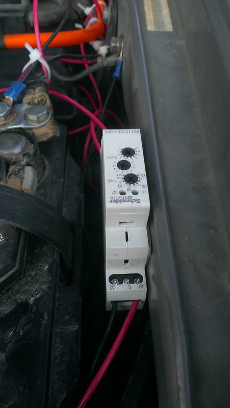
I'm not sure if you want any control over the actions of the solenoid, but this relay that I bought delays the joining for a few minutes after I've started the truck:
http://www.zoro.com/g/00062834/k-821TD10H-UNI/
9460788855_603528366c_c.jpg


My posts start here: http://www.expeditionportal.com/forum/threads/77503-How-to-make-a-cheap-isolated-dual-battery-setup-for-50?p=1402141#post1402141

I ended up using an add a circuit to the fuse box that was under the hood to get "key on" power.
 

FJRanger

I like getting lost...
Thanks for re-posting the info on the time delay relay. Going to run it in my to keep the 24v out of the 3rd/house battery and fuse block.
 

dwh

Tail-End Charlie
A review of the Lifeline manual (at least) will stress the importance of a charge source that sustains (not peaks) at over 14v

I repeat, my 1976 truck SUSTAINS 14.3v at any RPM above idle (once the batteries reach 14.3v surface charge). It only drops to 13.5v when the RPM drops to idle.


All too many chargers will, in fact, reach 14v, but when they do, they drop to a 13v float without completing the charge cycle.

That describes the behavior of a "2-stage" charger - bulk then drop to float. That doesn't describe the behavior of a 3-stage charger, nor does it describe the behavior of a typical RV "converter" which is often just a constant voltage (single stage) power supply.

Iota chargers without the IQ/4 brain module are 2-stage, and Progressive Dynamics (even WITH the Charge Wizard) are also actually 2-stage chargers. They both do a pretty good job of charging batteries.

Even at a float voltage of say 13.6v the battery WILL still absorb.


The result is that the battery is never fully recharged and then loses the ability to ever take a full charge.

See above. Again, the battery WILL still continue to absorb even at float voltage and WILL eventually reach full charge.

Also, all lead-acid batteries lose capacity over time. Proper and timely recharging to full can slow that down so the batteries will last longer, but, they'll still lose capacity.

However, that has nothing to do with reaching a "full charge". A battery, say 100ah, which has lost say 50% of its capacity, is a 50ah battery - but it will still reach a FULL charge of 12.8v resting voltage and behave normally. It'll be dead in half the time because it has half the capacity it once had, but it'll still be a fully charged 50ah battery.


(And I gotta tell you, the generalizing you tend to do with "13v this" and "14v that" disturbs me. It's way too imprecise - and for the laymen out there, possibly even deceptive. To say "13v is bad and 14v is good" doesn't mean jack when the 13v you are referring to is actually 13.9v. Bulk charging to 14.4v is different than bulking to 14.8v, and both are quite a bit different than bulking to "14v". Floating at 13.6v is a helluva lot different than floating at "13v".)
 

nsgoldberg

New member
This was a great thread until dwh and DiploStrat whipped their members out and had a pissing competition. And yes, this is my first post. Hi.
 

dwh

Tail-End Charlie
Yea, hey, hi. Welcome to ExPo.

I'm not having a pissing contest, I'm trying to get accurate information presented rather than misinformation. I do that to try to help others who are trying to understand how all this electro-crap works.
 

Forum statistics

Threads
188,243
Messages
2,904,462
Members
229,805
Latest member
Chonker LMTV
Top