Long Jeep.....chasing unicorns

MotoDave

Explorer
I will probably use some custom defrost ducts from vintage air in the top of the dash connected to a later YJ heater unit.

I'll admit i am biased, but I love the look of the Scout 80 defrost ducts
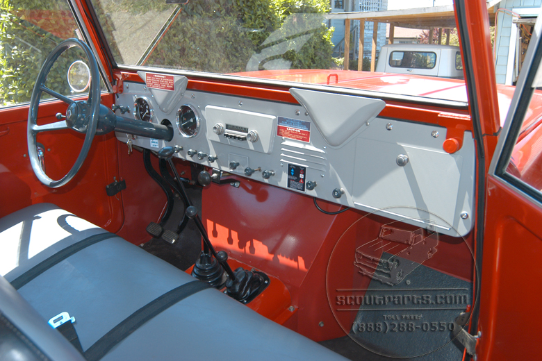
1961%20Scout%20%20glove%20box%20defrost.jpg
 

Metcalf

Expedition Leader
Some more misc butt end of the jeep stuff....


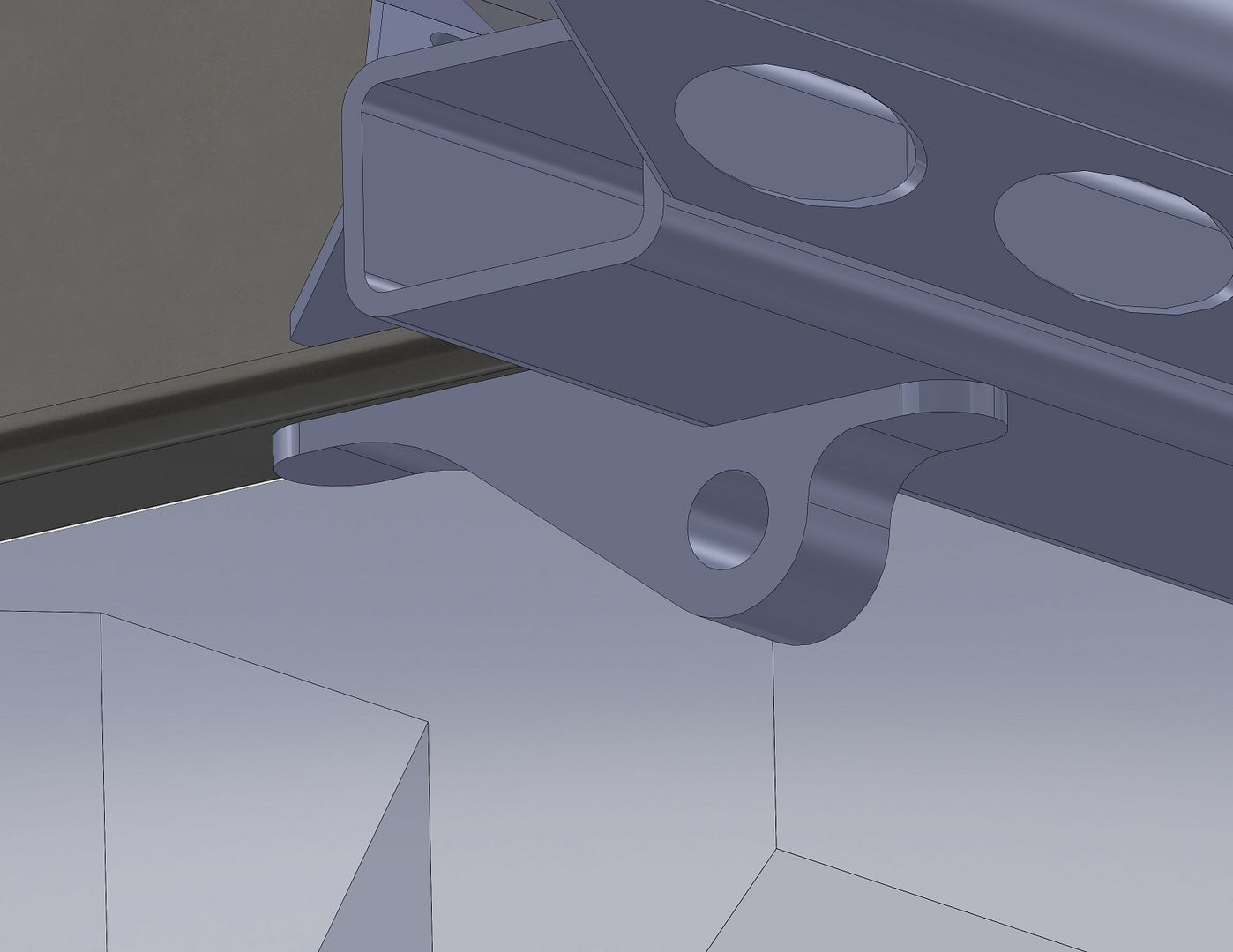
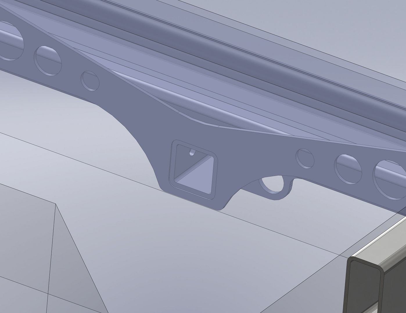
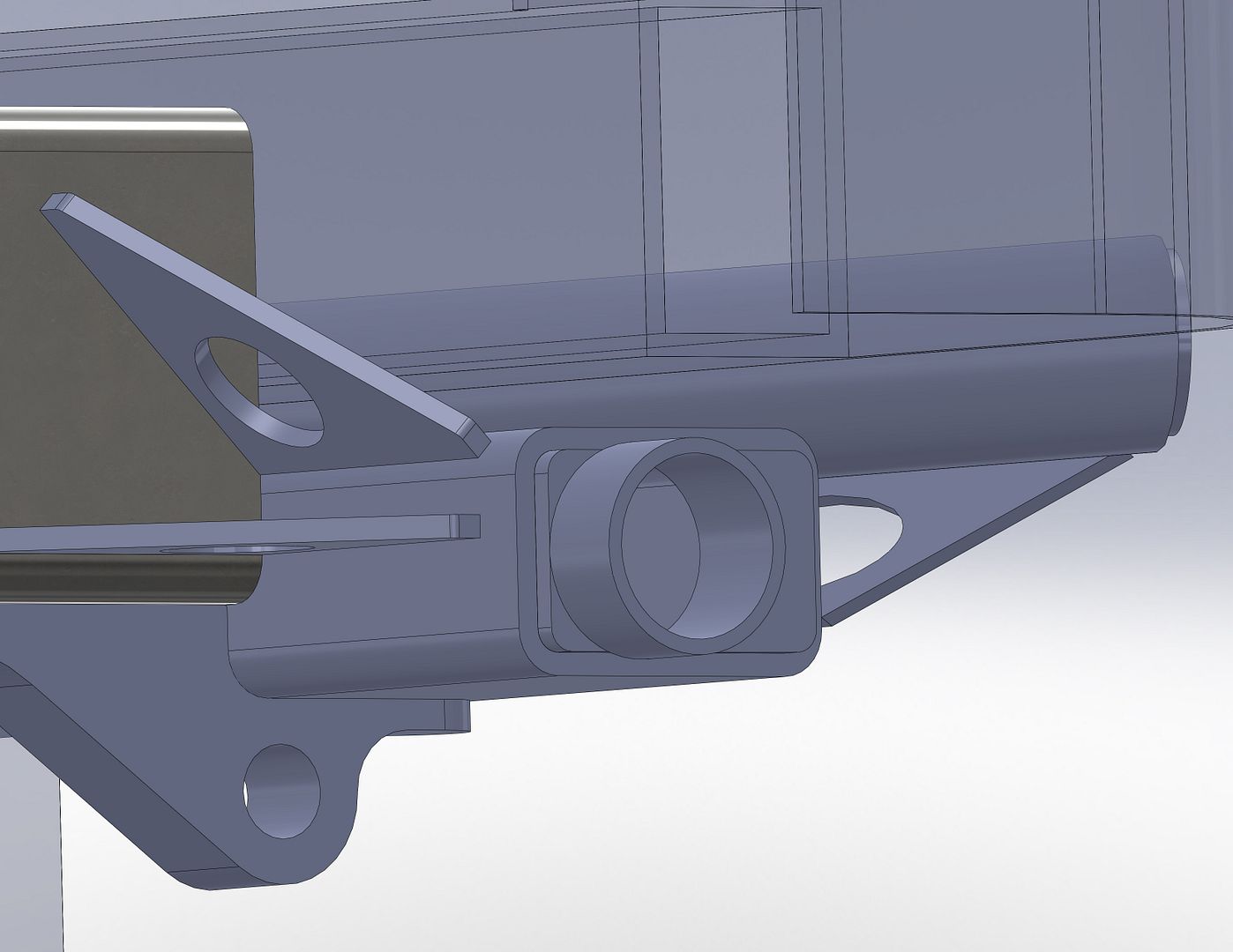
I beefed up these little profile cut parts. They now have an integrated 5/8 shackle mount also. The position isn't idea for recovery since they are slighty hidden under the rear bumper. I would probably use the rear hitch most of the time. They are now MUCH improved to deal with the twisting load of the rear crossmember that the hitch is attached to.


I changed the rear brace/gusset to wrap around the rear end of the hitch. It doesn't get in the way and is a 'free' part. The geometry just worked out nice to add it. It was kept short so there was still a mounting area on bottom of the rear crossmember for the fuel tank.


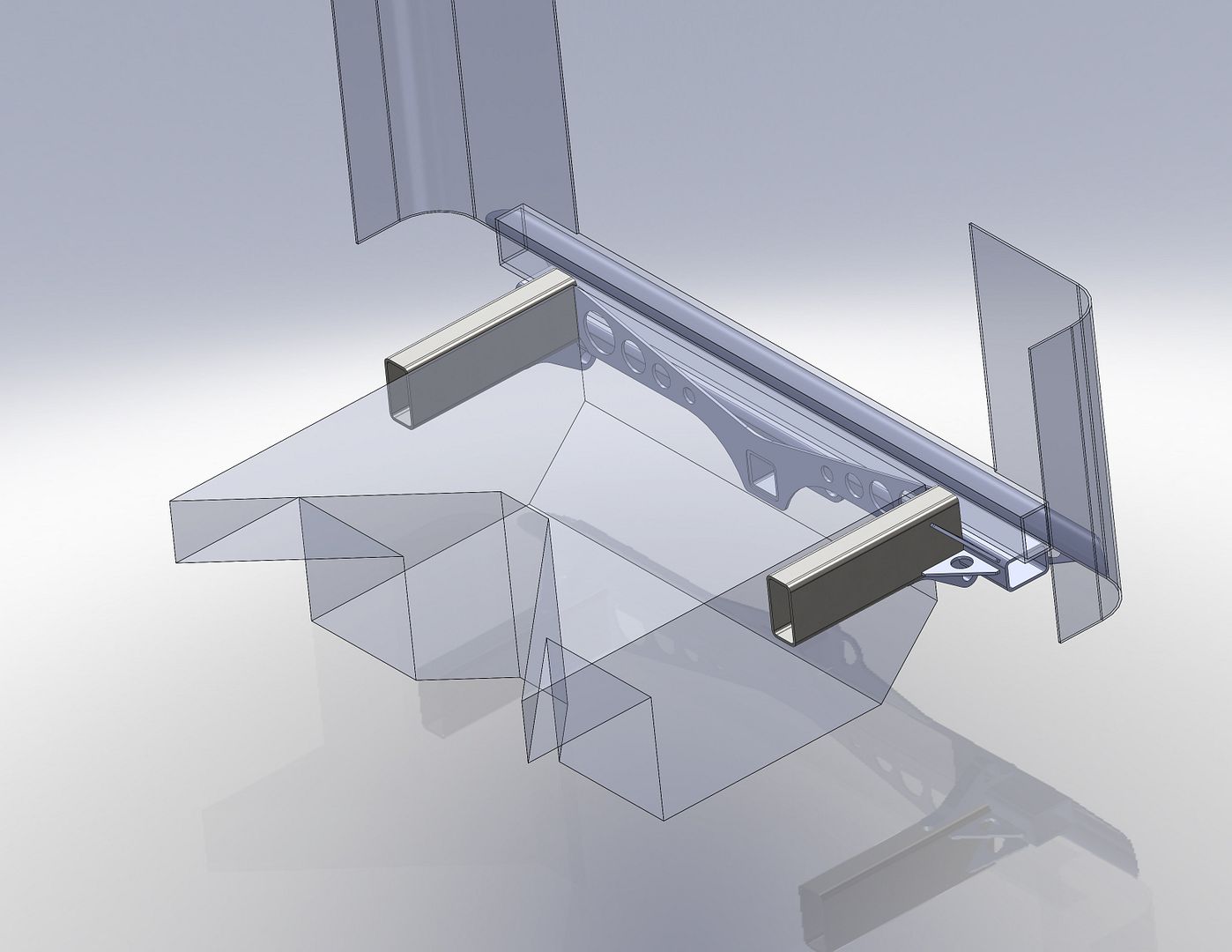
I also started playing around with the shape of the fuel tank. This is all kinda best guess stuff right now but it is interesting to get a feel for how much fuel capacity I should be able to get behind the rear axle. This tank only hangs 8" below the frame rail for a total of 12" tall. 29.5" wide and about 20" front to back minus the 'wings' on the front. The rough capacity of this tank is just about 29 gallons. I need to do a little more layout and see where the bottom of the tank can go. Adding 1-2" to the tank depth would bring the capacity over 30 gallons I think without having to have the 'wings'

Designing a fill port for the tank to work with this frame is interesting. There just isn't a lot of great options with the frame so high and tight to the body. The 'easy' thing to do would be to make a little tunnel in the body for the fill hole to go over the rail. I really want the tank to be able to drop out the bottom of the frame easily. I am also going to try and add a removeable access panel in the tub to allow the fuel pump assembly to be pulled without having to drop the tank.
 

Metcalf

Expedition Leader
Still futzing around with some layout on the rear of the chassis.


Some end cap swaybar adapters. This should seal up the rear crossmember from the elements for the most part. The frame is designed to use a standard 45" wide anti-rock swaybar package. That should get the swaybar outside the 40" wide wheel tubs with a little room to spare. I think the arms will have to be bent a little to clear the shocks....


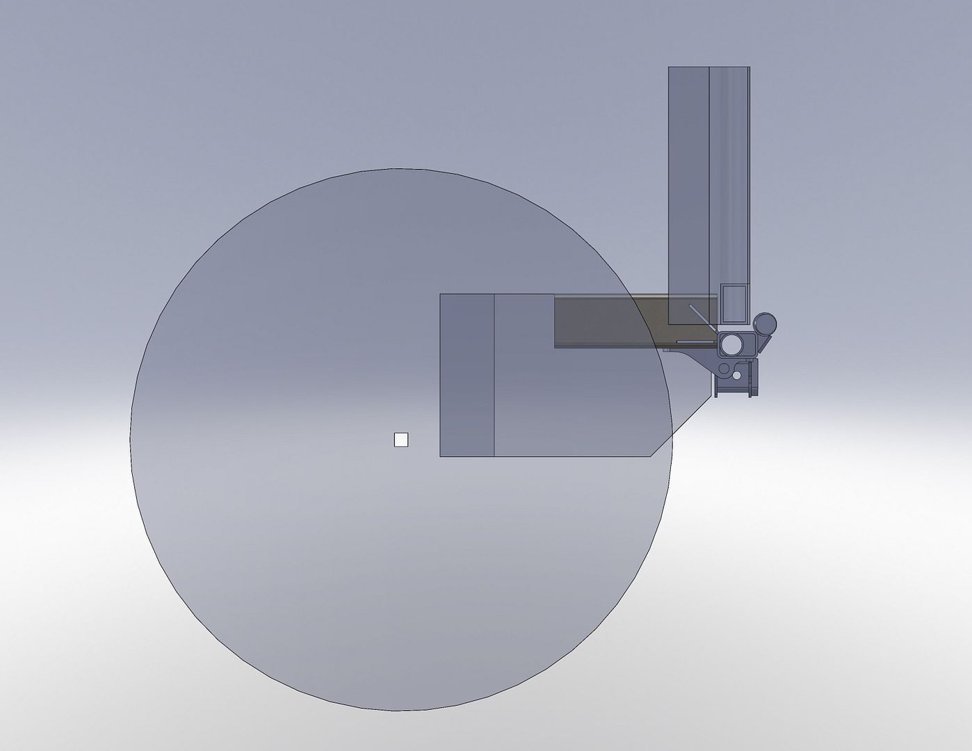
Here is a very rough layout of the rear of the chassis with a 40" tire close to ride height. The departure angle is 55 degrees at the bottom of the receiver hitch. The rest of the rear crossmember is much more out of the way.

The shape of the fuel tank looks close but I worry about the depth. With the chassis sitting this low there isn't really a ton of depth for the fuel tank. Having the tank hang below the axle tube at ride height is probably a bad idea. I think the tank will have to be below the axle tube on full compression for sure. Most TJ fuel tanks are set up very close to this. I like having the back corner of the tank cut off. That was always one of my major gripes with the TJ tank diaper shape. It also looks like the tank will have to get a bit shorter front to back.

I would really like to get a decent capacity tank in the chassis but with the triangulated 4-link there is not a ton of room. 30 gallons would be about right I think. I don't really want to make dual tanks. I don't need the extra capacity THAT much and packing around an empty 2nd tank would be the best. There just isn't a ton of room in the chassis even though it is about twice the size as my Willys! Having the room to store some fuel cans will be an added bonus....
 

Metcalf

Expedition Leader
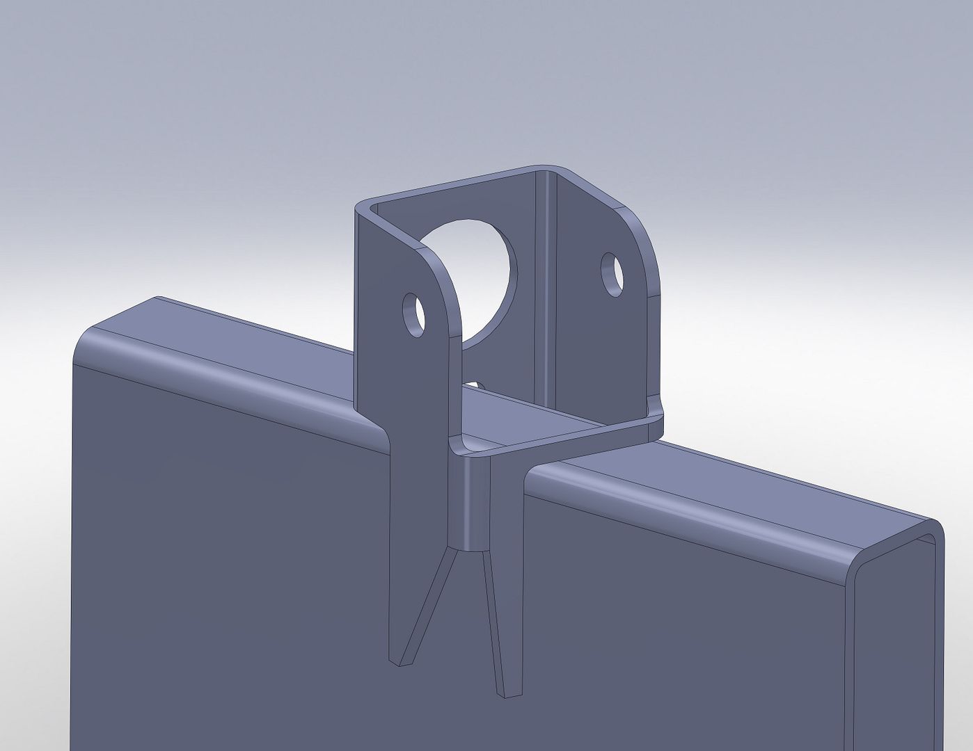
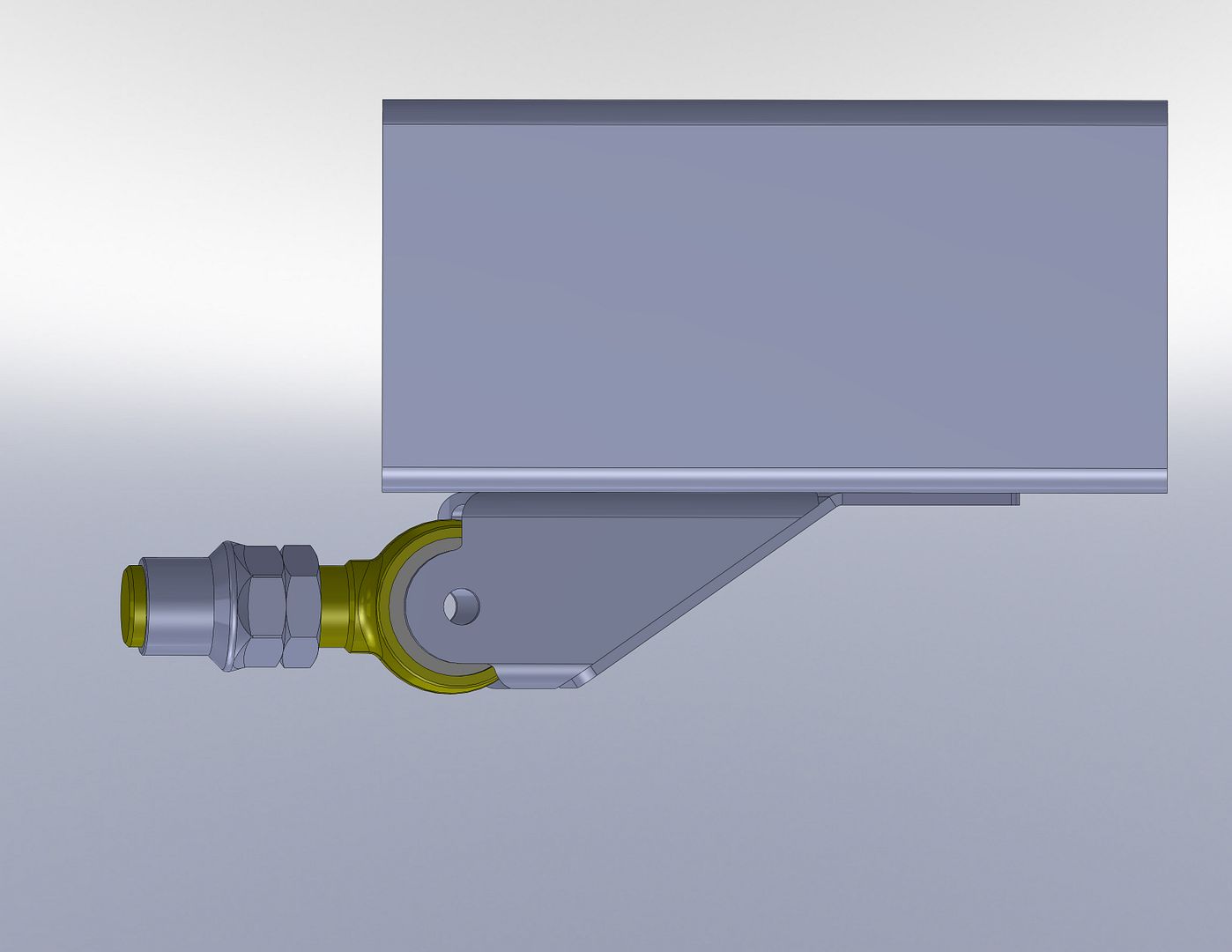
Not much today. I started designing a rough model of the front and rear suspension. I still need some more info on the tub and front clip to finish off the frame but I have a fairly solid idea on the shape of the frame and where the control arm mounts will be. Here is one of the brackets.......


What a pain in the rear to get right! I am trying to design the brackets to be made from 3x3, 3/16" wall tubing and to use a common 2.625" wide bushing, joint, or rod end. I use a laser tube machine out of California sometimes for work. They can cut stuff like this pretty easy, and affordability, if the solid modeling is done right.

This is the upper rear frame side link mount. It is designed to fit under the floor on top of the frame just before it kicks up. The angle is set but the suspension layout. The arm is angled in approx 22.5 degrees from the frame. The joint is pretty tight in the bracket but should have enough room to move around. The joint center is 1.75" above the top of the frame and the pivot is inline with the center of the frame.

I am trying to keep all the links the same rough length in the suspension design so that a common spare can be used. The panhard bar in front will be the exception. Control arm length is going to be pretty conservative at about 28" long.

As things progress hopefully I will be able to work up a complete model of the frame and suspension....
 

Metcalf

Expedition Leader
Just one more for today....


This is the rear lower frame side bracket......drivers side. The same parts can be used to make the passenger side bracket even though its a mirror. The main housing is the same 3x3 tubing but the gusset mounts are all 3/16" plate same as a lot of the other brackets on the chassis. The link mount is basically flush to the bottom of the center 6" tall belly section of the frame. There is a 3/16" gusset that goes on the bottom of the frame but that is SOOOO much stronger than welding everything to the side of the frame. I'm still not 100% happy with this bracket and will probably tinker with it some more.

The rear lower arms mount above the bottom of the frame to eliminate the common snag point of the rear control arms on the rear suspension. Because of the low stance of the vehicle the arm angles are kept in check. Estimates on the rear suspension are 50-60% AS static, 3 degree positive roll axis, 28" long common arms, nice long instant center, 45 degrees triangulation on the upper links and 14 degrees on the lower links. Some things in the rear suspension geometry are compromises for a little bit more clearance on the lower arms.....

Fun Fun

Edit: A big thanks to MotoDave for the joint model....that saved me a lot of time!
 

jeepdreamer

Expedition Leader
Ok.... I'm gonna admit that while I know your project will be jaw dropping when you get going on it, I'm stymied at the computer renderings. I (sadly) have no idea how one does stuff like that on a computer. Sure wish I did because it could be helpful for designing my custom tool trailer. *sigh*
Ok... back to offering moral support. :)
 

Metcalf

Expedition Leader
Ok.... I'm gonna admit that while I know your project will be jaw dropping when you get going on it, I'm stymied at the computer renderings. I (sadly) have no idea how one does stuff like that on a computer. Sure wish I did because it could be helpful for designing my custom tool trailer. *sigh*
Ok... back to offering moral support. :)

I know the computer stuff is a little boring. Sadly that is all I have to offer on this project right now. This project is going to be a pretty long and complex one. While most of the project is firmly in my head, I need to get a decent amount of it into the computer.....

I hope buy computer designing a lot of the parts ahead of time I will be able to save a lot of money on CNC cutting hopefully.

I design things for a living in Solidworks, so doing this kinda stuff is just 'fun' during lunch and off times. I basically think in 3D modeling these days....
 

Metcalf

Expedition Leader
Oh I don't think its boring at all. I have no idea how its done and think its cool. I just wish I could do it myself. :)

It's not really that hard at all. Having access to the program is the hard part. Being able to do something with the information is the other thing. I made a LOT of 100% scale paper templates for my Willys build. Just that ability came in very handy. This build will hopefully utilize a lot more computer cutting. If I can get far enough ahead of the curve in planning out parts I should be able to get large batches of parts cut for a decent cost. I have a local waterjet table with a 5-axis head that I work with a lot too.

Never to late to learn Solidworks. There is a student edition out there that is pretty affordable....
 

Metcalf

Expedition Leader
I am still working through the suspension design stuff. Most all of this stuff is modular and can be used on just about any frame design so it doesn't matter if I have final dimensions on the frame rail length. I do have the option of just sending the entire package off to the laser tube cutter. Basically, if I get the design far enough along I can order a bunch of parts that will go together like Lego's. The only thing I should need is a few simple jig plates. I am trying to design things in a way that the same part can be used more than once....and in as many places as I can think of to minimize overall part count and complexity.

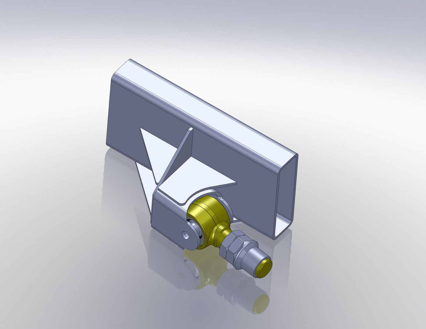
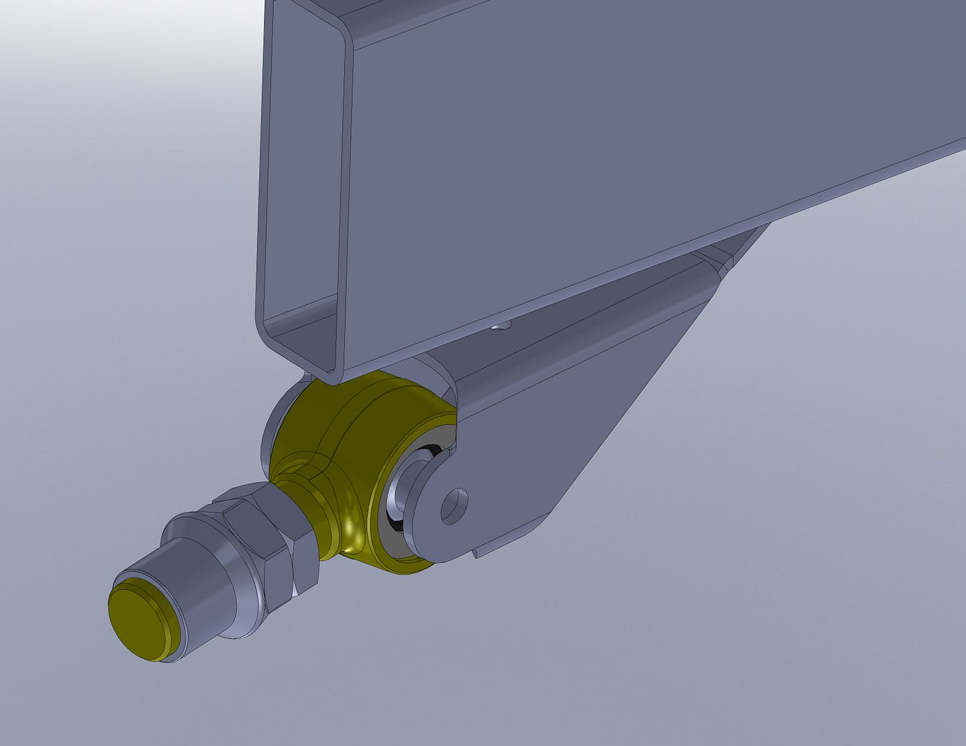
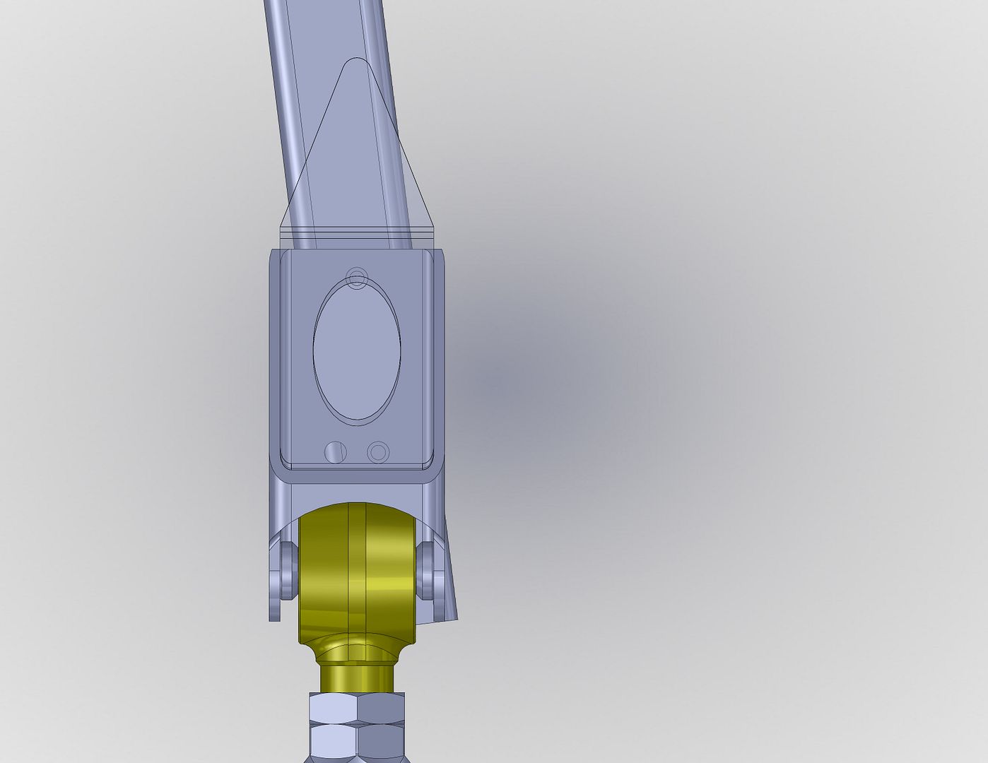
Anyways....blah blah blah.....here is the front lower frame side control arm mount design.


The main bracket is cut from the same 3x3 3/16" wall tubing as most of the other brackets. The gusset is 3/16 plate with a simple bend to form the tail that gets welded to the bottom of the frame. The bracket has a set of alignment holes you can see in the 3rd picture. These holes are mirrored so that the same bracket can be used on either side. The bracket is designed to be angled out 7 degrees from parallel. This 7 degrees is the same as the rear lowers also. This should allow me to use a common lower control arm mount on all 4 axle side mounts if I get the design right.
 

Forum statistics

Threads
188,476
Messages
2,905,642
Members
230,428
Latest member
jacob_lashell
Top