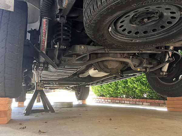
Los Angeles -Class Attack Sub(urban), Build / Collected Werks topic - '02 k1500 Z71

rayra

Expedition Leader
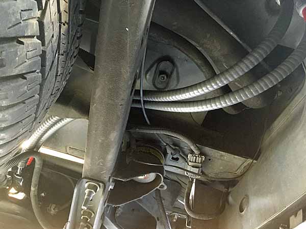
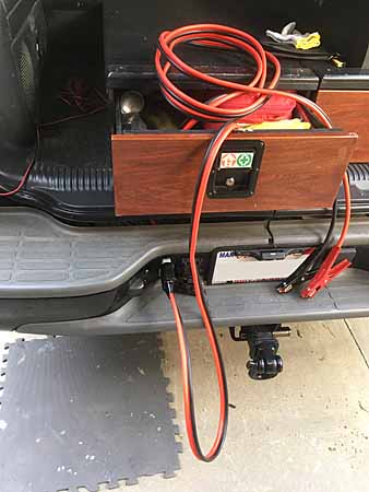
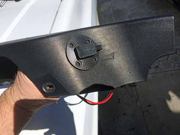
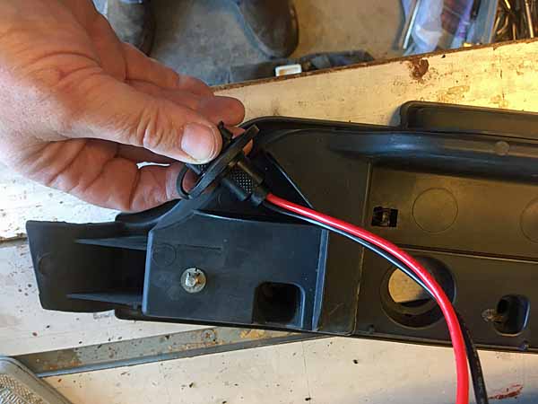
Working on the cables installs to the rear bumper plug, a little extra complicated with trying to put a weather boot and PVC conduit on the cables for water, mud, debris protection on the back side of the rear plug. As well as the boot in the front face of the plug. I'd though I'd had some sort of fitment problem when I tried to plug the jumper cables in last night. So I pulled the bracket to check things out. Turns out that I'd just left the loop on the external weather loop in the wrong spot, interfered with fully seating the connector. So now it's moved.
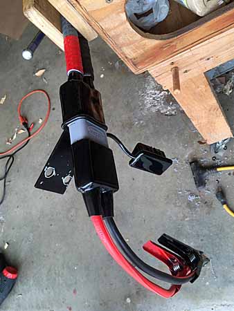
winch153 rear plug bracket conduit.jpg


The way I arranged the bumper bracket and trimmed the bolts attachign the plug to the bracket, I'm able to fullt seat the back side boot fully up on the plug. The conduit runs will just seat over the tips on the plug boot. After the cable conduit bulkhead fittings are secured to the cargo floor and the other ends of the cables cut to length and terminated and that plug mounted, I'll go back under and shove the conduit away a little and slather some 100% silicone on the taped cable and boot ends and bring the conduit back into full contact, slather some more on and around those joins, then anchor the conduits to the vehicle frame etc.
It's all overkill for the desert southwest, and I try to stay out of the mud.


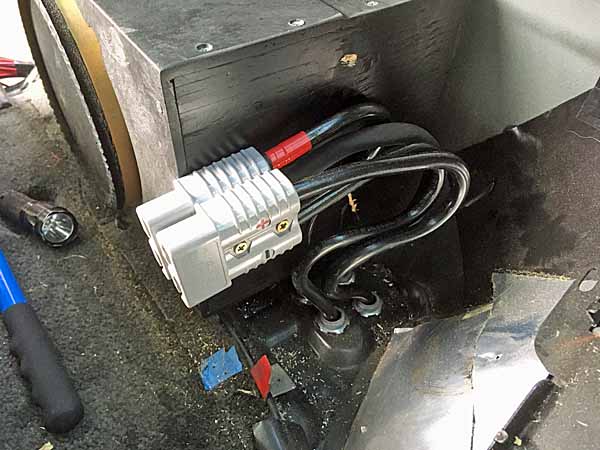
Here's the factory Subwoofer box. I cut about 3"+ off the right end to make space for these cable runs. I'll have a better pic later when I get this last pair in. But the four floor penetrations for the double pair of cables was planned for a few years ago when I began the project. So the conduit and cable will just fit.

winch152 rear plug subwoof.jpg


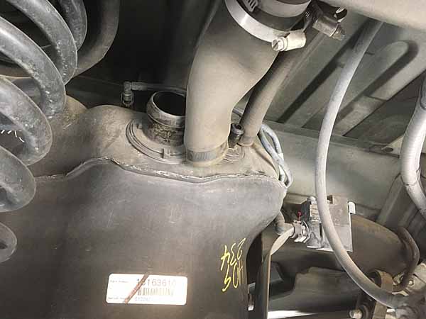
The subwoof box is about 3" deep at the floor and left side, pretty much the area of the speaker itself, with a larger deeper box on teh right half. The fuel filler is basically right behind the speaker. The box is about 11" tall from the floor and about 1" under the bread box. And about 12"L . I thinking to pull the sub altogether and put in an air compressor there and hard plumb it to both ends of the vehicle, too.

Late lunch is over, time to go try and wrap this rear power plug hookup before it gets dark. Rain is starting tonight and is expected for the next 5 days, so I really had to curtail my project plans for this week.
 

rayra

Expedition Leader
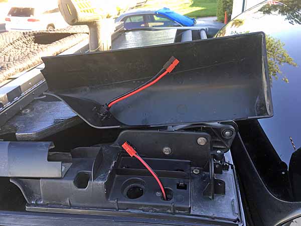
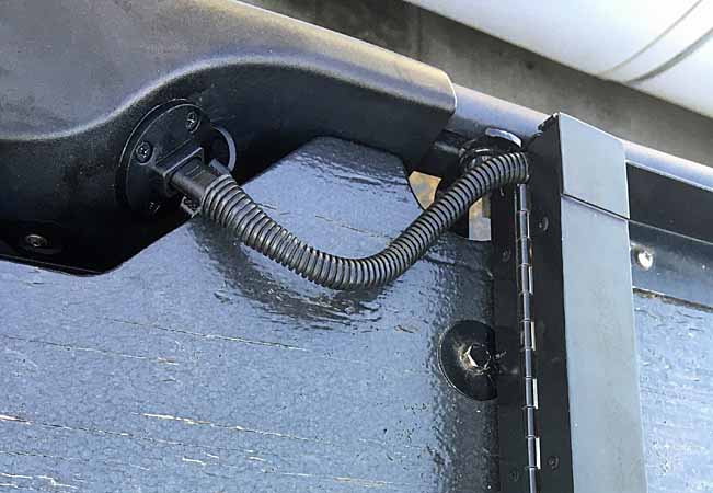
Got the rear plug cable and conduit installed, the cargo sidewall plug doubled. Got things back together before the rains cam. Working on the cable runs inside the power module box tonight, inside the garage. Maybe tomorrow, I'm pretty tired.

winch155 rear plug conduits.jpg
winch156 rear plug cargo plugs.jpg
winch157 rear plug jumper cables.jpg


Once the plug and cable are added into the power module, the rear plug can be hot and controlled by the big white rotary cutoff inside that box.
 

jgaz

Adventurer
That rear jumper cable plug is sweet! Nice work.
We had three on the wrecker we used at work, one front and one on each side in the rear. Very handy.

Having the jumper cables terminated on one end with the Anderson connector had the added benefit of making the cables useless for someone who wanted to borrow them for another job.
This meant the cables were always with the wrecker and not where some lazy ass left them when he was through with them.
 

rayra

Expedition Leader
Yeah that's a good way, heh. I've got the other end still with them, but I put the anderson couplings in there so I can use them either way. In fact I hadn't factored in the jumper cable setup in my bigger Anderson parts order from powerwerx and had to order some more stuff to replace what I used on the jumpers, so I can complete the front plug cabling too. I still have to fashion the firewall mounting plate for the rotary cutoff, so between that and the rains I'm not really delayed by the parts diversion.
 

rayra

Expedition Leader
Spent some more time bundled up in the chill garage, working on finishing the plug cabling for the rear power box, last of the work to make the rear bumper plug hot. Works great.
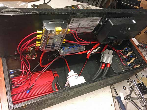
I'd initially measured the short cables for use in that block by matching the other plug run. That was a mistake, as the new plug is 'inboard' of the original so the cable run is necessarily a bit shorter. So made the necessary adjustments before consuming the freshly arrived anderson terminal lugs. Also made a new short run for the (+) on the 1000W inverter, as I changed the routing a bit. One of these days I'll diagram the mess.* Got a lot of stuff going on in a confined space.
Double-checked and the less costly rotary switch I put in the rear box is rated at 275A continuous. The Big Red rotary from Blue Sea I'm using under the hood for the front plug is rated at 300A continuous and is a lot more robust. For a +80% premium it had better be.
Anyway, a few pics of the layout in the box with the new doubled plug setup and the last pic is everything back in the vehicle and fully plugged in.

winch158 rear power box.jpg
winch159 rear power box.jpg
winch160 rear power box.jpg
winch161 rear power box.jpg
winch162 rear power box.jpg
winch163 rear power box.jpg


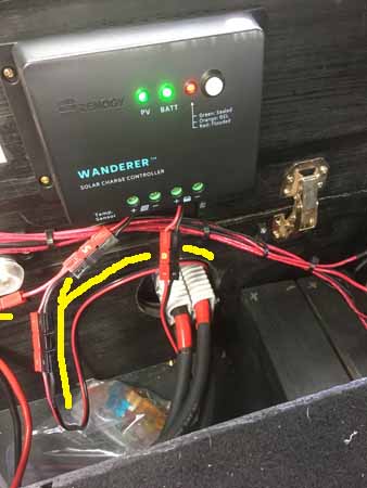
* The pair of cables from the under-hood Aux battery run under the vehicle, each encased in flexible PVC conduit along the top of the passenger side frame rail, across forward of the rear axle and up thru the floor behind the driver side rear wheel tub, ending at an SB175 connector in the cargo side wall. That mates with the like plug inside the rear power module. The (+) runs a terminal stud to the rotary switch. A 4ga (6?) wire from that same stud feeds the aux fuse panel in the module that feeds power to all the panel mount power connectors and inverters installed in both faces of the rear power module. The battery (+) from teh solar PWM controller also connects there, charging the Aux battery.
The other terminal stud in the rotary switch has a cable feeding the 1000W inverter, been that way since the beginning, have to turn the rotary switch to power the inverter (which has its own faceplate switch). It now also has the new 1/0 cable going right back to the new added SB175 plug. Which in turn connects to the new plug in the cargo sidewall which runs back thru the floor and in conduit back to the rear bumper plug. So the plug is dead until the rotary sw is turned on.
The power module has a common ground terminal stud fixed in the bottom of the box, all the negative / ground leads are bolted there.
All the panel-mount devices in the box are individually fused and all their negatives run to a common bus bar, which is itself wired to that common (-) terminal stud.

My original mockup for this power module included (4) 10Ah wheelchair batts for extra power, in wood mockup form. I may still do this in the future, but have to isolate things so they get charged, but discharge separately from the Aux. TBD.

More proximate plans include an 'on board air' capacity, probably mounted in the cargo area in place of the subwoofer. And it will probably be powered and controlled via this power box, with its switch on the rear facing panel of the module.
 

rayra

Expedition Leader
I'm Crimpin' In The Rain, Just Crimpin' In The Rain ...

winch170 front plug crimpin.jpg


Well it's done. No shorts, no shocks, no burns, no fire. The final test was anticlimactic. No ZOT, no nothing. Didn't even burn up the free meter.

couple explanatory shots of the 'power module' end plates, their variety of connections -

winch164 rear power box.jpg
winch165 rear power box.jpg


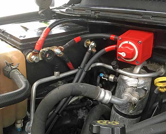
some work on the mounting plate for the rotary switch. The two hex-heads are the former mount location of the solenoid, now serving to mount the adapter plate I fashioned for relocating and mounting the Blue Sea rotary cutoff switch for the front grill plug.

winch167 front plug rotary.jpg
winch166 front plug rotary.jpg


and some word salad describing that mess.

winch168 front plug rotary.jpg


winch170 front plug crimpin.jpg
winch171 front plug batman.jpg
winch172 front plug.jpg


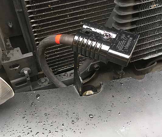
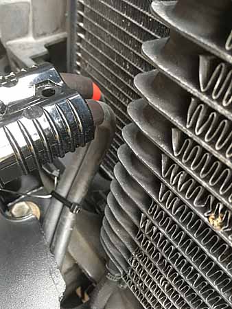
The cables to the front grill plug go forward and down along the AC plumbing, along the front wheel tub, sheltered from any road debris. They cross the top of the frame rail before the radiator and dip down and under the radiator and up in front of it thru the trans cooler plumbing penetration, to the grill plug. I have them zip tied for now, will do that again with better-suited ties later. It's good enough to drive around with, now. In this pic you can see the pair of cables for the front plug zip-tied together.

winch173 front plug.jpg


When it was all done I turned the rotary switch. It was just like turning it on the workbench. No pop, no smoke, no nothing. Stuck a meter in the front plug just for the hell of it.

winch174 front plug.jpg


There's some tiding up to do, some better cable securing to do at a later date. But that's it. To paraphrase Andrew Camarata, 'that's done, on to the next project'


eta I also decided that I was finally done screwing around with all the front steering, suspension replacements and adjustments, settled on a ride height and finally got a proper alignment. Was starting to chew up my older pair of tires in all sorts of interesting ways, finally got my fairly fresh pair on front where they belong, in the middle of weeks of rain storms around here.
 
Last edited:

rayra

Expedition Leader
cleaned up a lot of messes in the garage on this long rainy day. All the detritus from the wiring projects, the bags and boxes of parts, taking a little inventory for remaining projects, the roof rack bulkhead connector for the rooftop solar panel is next when it stops raining. And sorting a lot of hardware messes, screws, bolts, lot of leftover mixed piles of stuff accumulated from a stream of projects. Upside being it will make things easier to find and cut down on buying stuff I already had.

winch176 what a mess.jpg


Also made a 'parking spot' for the winch cradle. Added a new cross brace to some rolling shelves full of car related stuff, cut a 2" hole thru it and put a steel plate brace across the bottom, winch and carrie rwill be about 90# when it's done. Place to store it (with the winch installed) when I don't have it on the vehicle. And when I start work on sewing the 1000D fabric / zippered cover for that setup I can work on it freely right as it sits.

winch175 cradle parking.jpg


I cheaped out during this period of covid unemployment, once again back to more time than money. And as I might be towing a camper trailer around later this summer, I want to get new springs in, new rear bearings, and need to dismantle and lube as much of the rear squeaky suspension as I can. And I figure the new springs will take out a lot of the remaining body roll.
The Moog HD springs are 17-1/4" tall uninstalled. Somewhere back in this topic 2yrs? ago was the last time I had the original rear springs out, adding a taller spacer and swapping them side for side to level out the vehicle. I can't remember what their heights were then. I'll see when they are out and decide if I'm taking the 2" spacer back out and putting the ~3/4"? spacer that came with the leveling kit back in, or leaving spacers out altogether. Whatever works to keep it at the height it is now.

coil springs new moog 200409.jpg


But the next non-rain day project is cutting in the new bulkhead connector for the rooftop solar, into the left rear roof rack mount / shoe. And I have to get the new fuel pump in, change 4 u-joints. Finish the fuel tank plate template. And I guess while it's up in the air I'll swap in the new coils.

Next batch project after that will be replacing / upgrading the rear brake rotors and pads to the Powerstop Z23 set. To finally match the front. Change the rear axle bearings (Delco / Timkin) and seals.
 

rayra

Expedition Leader
Did the re-wiring of the rooftop solar today, thru the footing of the Z-71 roof rack, thru a bolt hole in the roof. Previously the wiring trailed off the roof and tucked in at the top of the Liftgate and down along the Liftgate opening gasket to the bottom with a drip-loop sort of arrangement and in at the bottom over the gasket.

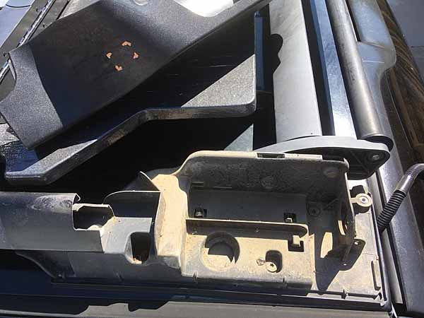
Here's the driver rear roof rack footing / shoe during disassembly. A couple T10 torx screws on the inboard face of the shell and it lifts right off. A 10mm nut attaches the end of the side rail to the inner shoe. (2) 10mm bolts tie rear airfoil and roller to the shoe. It was a little dirty inside and underneath everything. There's (3) T25 bolts that hold the whole corner to the roof. The red arrow is the one I'm leaving out to pass the wiring thru the roof.

solarconnect012.jpg
solarconnect013.jpg
solarconnect015.jpg


There's a lot of room between the aero-shell and the shoe proper. The shoe is a clunky sort of thing and appears to have been designed with a lot of options to it. Chiefly a 1"dia hole thru both shoe and the bottom shim, right to the skin of the vehicle. Big enough to pass something as big as a radio antenna lead PL-259 connector. And the shoe itself has some fins to channel such an antenna cable.
So when I went to add the bulkhead connector for the solar power connection, it was an easy fit. The location on the shell I'd already chosen happened to line up quite well with the shoe. I would have chopped up the shoe as required if it hadn't, but as it was I just had to trim off one interior fin with a razor saw and that was all. Went right together after that, without any interference.

solarconnect014.jpg
solarconnect017.jpg
solarconnect018.jpg
solarconnect019.jpg


Another interesting bit I've read about elsewhere, that the Z-71 rack mount was prototyped to mount a rear-facing light. This was born out. A couple folks on other forums have mounted various 3" lights in this housing and I intend to in the future. There's room for all sorts of small light fixtures in there. I'd like to put some LED floods back there and power them both in sync with the backup lights and manually via a dash switch activation.

solarconnect016.jpg


And a couple shots putting things back together. I burned a couple Anderson Power Poles (APP) connectors in there, could have just used some bullet / crimp style connectors, but I just like the APPs better and I have a bunch laying around.
I made a new cable adapter, using the SAE connector off the bulkhead fitting, and an APP on the other end to connect to the solar panel in its roof mount frame. About a 14" run with some split loom jammed on there to shield the thing from the sun, also wedged in the gap in the frame. Frame isn't water-tight anyway, so that's good enough.

solarconnect020.jpg
solarconnect021.jpg
solarconnect022.jpg


didn't finish the interior wire routing yet, ran out of daylight. I'll finish that off tomorrow, routing behind the interior trim and thru the cargo wall hole like the heavy cables. I'll detail that later. Pulling the rear coat hanger hook to lower the ceiling panel was a PITA.
 

fnjeep314

Observer
Love your build! Can I ask for you to post a picture in this thread for Suburban builds?


Look forward to more updates!
 

rayra

Expedition Leader
already did, it's the one hiding behind the coyote brown awnings under the power windmills. I'll find / make a better 'action' shot soon, after I finish my winch setup.

--

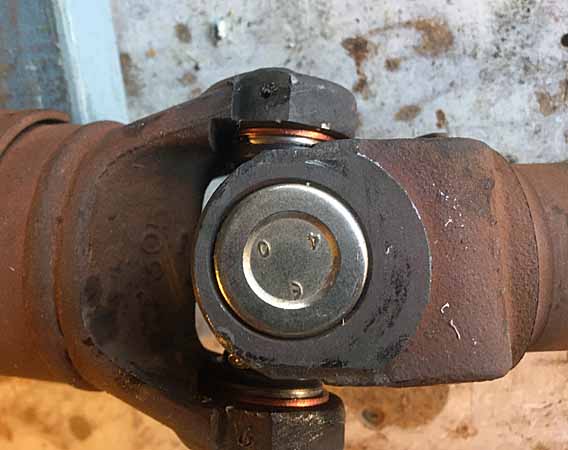
This afternoon I intend to finish the interior solar power wire routing, get that back together, then re-install some tow hooks under the rear frame ends WITH the tow hitch installed. And then possibly pull my front driveshaft for u-joint replacement this evening. But I think I'm nearly out of propane / MAPP gas for that. GM factory U-joint caps are typically anchored in place with an injected plastic which you have to melt to release. .
 

rayra

Expedition Leader
Got the rooftop solar wiring routed and taped down and thru the cargo sidewall opening like the heavy cables, everything working fine. Charging the battery at 14.6V

solarconnect023.jpg
solarconnect024.jpg


I also got my big steel tow hooks re-installed with the tow hitch in place. I used the forwardmost hitch frame bolt to mount the hook and drilled a new hole in the bottom of the frame thru the other hook hole, forward on the frame from the hitch. Used a couple washers as a shim fo rthe new hole, as the other part of the hook is on top of the hitch mount metal. I need to get a set of 1/2"x3" #8 bolts and nuts and re-work things. But the holes are drilled and things are bolted up well enough for now. Be an easy bolt switch later.


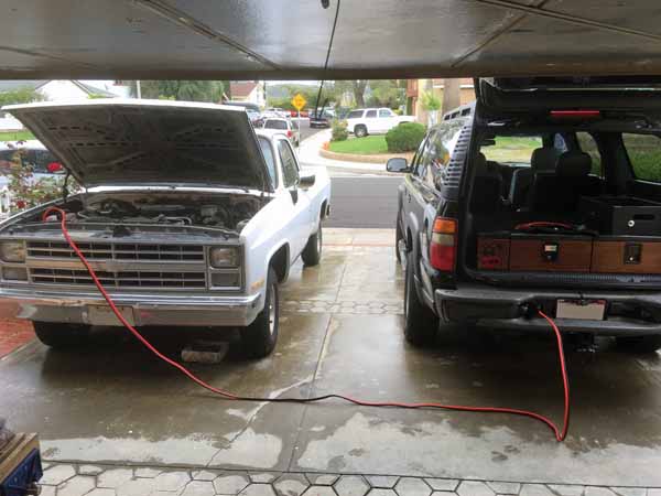
Then I balked at going after the front driveshaft u-joints. still having trouble with positional vertigo. So I decided to go ahead and jump the old Thunderbolt GreaseSlapper using the spiffy new rear power plug and modified new cables. Worked great. Only took about a minute to pass enough juice and the cables didn't even get warm.

jumperstreet.jpg


Definitely need more MAPP gas before I pull the driveshafts. Hope to start the fuel pump work Thurs afternoon.
 

rayra

Expedition Leader
Some stuff on GMT800 Z71 / Z82 Tow Package. Hoping to do some trailer towing / camping later this Summer, doing a string of projects now to make ready.

Stuff on the trailer connection. The Subs have a Tow/Haul mode with a gearshift button that activates an alteration in shift points, along with a 'heavy duty' 7-pin trailer connection and under-dash connection provision for a trailer brake controller. There's even a factory wiring harness available for it. The pic with the yellow arrow is the SEO connector I use as the keyed-on power for the battery combiner solenoid trigger.

towpackage01.jpg
towpackage02.jpg
towpackage03.jpg
towpackage04.jpg
towpackage05.jpg
towpackage06.jpg
towpackage07.jpg
towpackage08.jpg
towpackage09.jpg
towpackage10.jpg
towpackage11.jpg


CURT brand controller knob, looks interesting. I've been planning a switch panel atop my radio console, between it and the dash. This knob could go on the leftmost end of it. The controller is about $200.
https://www.etrailer.com/multi-prod...HHYear=2002&HHMake=Chevrolet&HHModel=Suburban
 

rayra

Expedition Leader
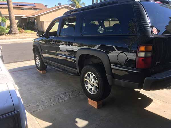
Messing with some Suburban undercarriage work this afternoon.
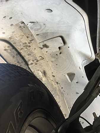
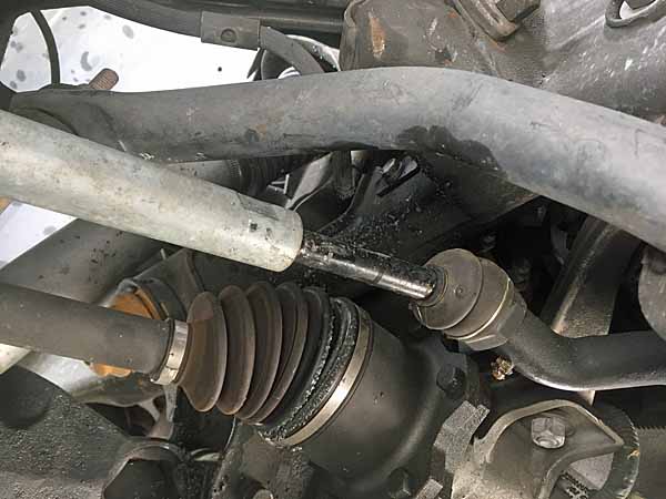
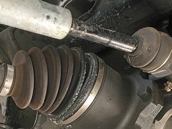
Noticed I had some grease splatter in the passenger front wheel tub, day before the front end alignment and forgot about it until today. Forgot to ask or look during the alignment. And that worthy didn't mention anything to me. Jacked things up today to go after the u-joints on the front drive shaft and while it was in the air I wiped the mess up and gave the CV joint bellows a cursory inspection and found no splits or tear. But I need to find the source. The goop looked just like the stuff in the guts of a CV. One of these new ones pulled apart on me during install a few months ago, I had the clamped seal apart and back together and can't recall which side it was on. I suppose it was this one, will have to figure it out.

CVbootleak01.jpg
CVbootleak02.jpg
CVbootleak03.jpg


I'll dig into the images tonight and make a more determined inspection while I still have it in the air, in the morning.


Then it was on to today's project. I've got some play still somewhere in the front end. Still an alarming clunk once in a while and I still can't find a source. But at 146k it's time for some new u-joints already, and bought all four new about a year ago. Given that it took me 20-some years to get around to installing the last set after I bought them (in my C-10), I figured a year was long enough already. Ironically, they're still the very same part / size, 1985 C-10 and 2002 K1500 Suburban. Good old GM, cheap / lazy fastardos.
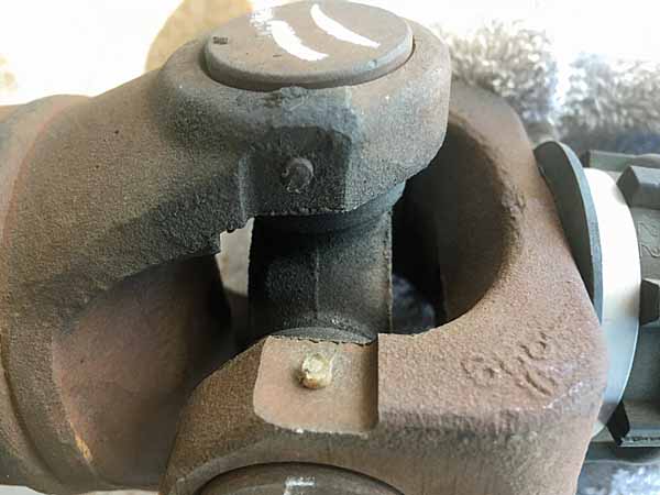
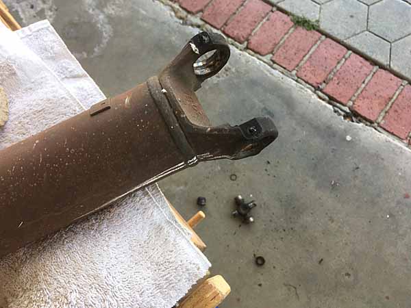
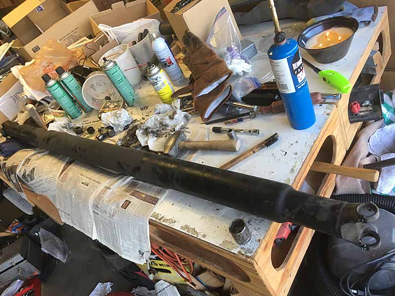
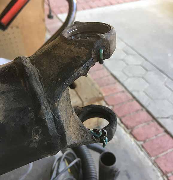
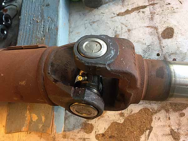
And unfortunately that means the same molten-plastic-locked U-joint caps. Which you either have to melt out with a torch (FIRE FIRE) or press out with a 20-30ton press. I elected to use the former again. I didn't take as many pics this time, was in a hurry, and I'd documented this process before, ~18mos ago with the C-10.
So I go busy heating them up and knocking things out. But just got the front driveshaft back together before dinner and called off the reassembly until tomorrow.

ujoints01.jpg
ujoints02.jpg
ujoints03.jpg
ujoints04.jpg


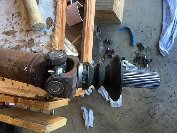
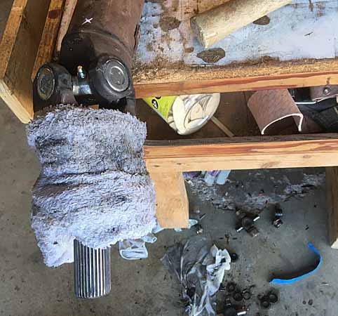
The only thing different this time was the presence of a clamped on rubber boot on the output shaft that sticks in the transfer case. I didn't have a replacement handy and didn't want to screw with rtying to slide it off or mess with its clamp, so I elected to wrap that boot with a soaking wet towel and orient the yoke so all the torch heat was moving up and away from the boot. I seem to have got away with it.

Anyway, you heat the yoke until the nylon-plastic come boiling out of the weep holes in the yoke armature and then you punch or strike out the caps. A real metal bench and large vise is an asset for this sort of thing. I had neither and scorched my wookworking table a little. But I got it done and carefully clamped and tapped back together.

A couple pics from the C-10 driveshaft work as illustration

pickup ujoints 01.jpg
pickup ujoints 02.jpg
pickup ujoints 03.jpg


Tomorrow I'll probably repeated the process with the rear driveshaft, as a prelude to pulling the fuel tank. Was planning to remove the rear drive shaft anyway to gain room to work on the fuel pump swap.
 

rayra

Expedition Leader
re-post from Hey Vortec Guys, putting fresh mechanical repair stuff in both topics, not sure who is following which.

This morning it was reinstalling the front shaft and turning a test drive into a cheeseburger hunt at lunchtime. After I came back my magician's assistant was able to slowly inch the vehicle backward in the driveway while I lay under it seeking the perfect angle to access the grease fitting on the frontmost u-joint. No worries, I had a large rubber wheel chock between the front tire and my rib cage.

/there's a reason I don't have a large life insurance policy, I'm worth more alive than dead.


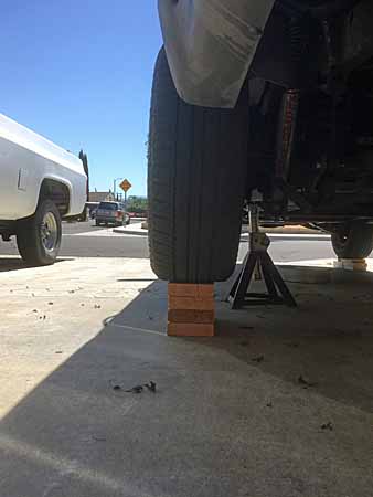
Then the afternoon I rigged the Suburban on the redneck hoist in preparation for the fuel pump replacement and kicked that off with the rear driveshaft removal and new u-joints in it.

fuelpump001.jpg


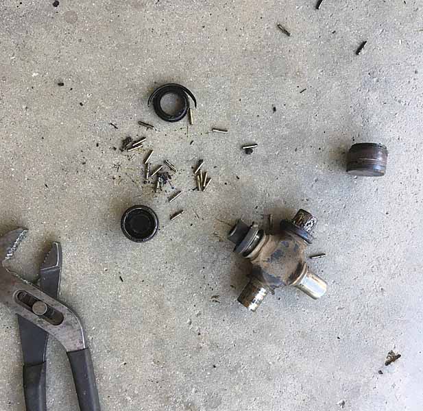
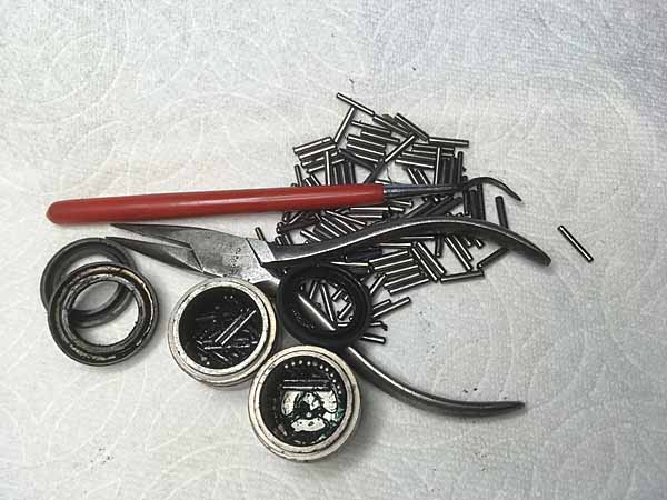
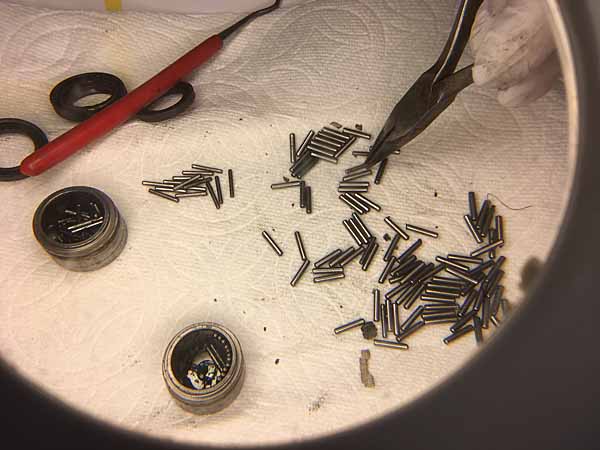
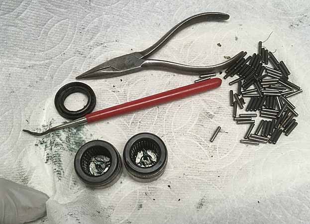
That was going well enough, melted off 4 caps, got the rear end joint fitted, even got the grease fitting facing the right way, then I got the joint set in the front end of the shaft, with the other two bearing caps careful set to the side [in creative writing this is called foreshadowing], while I gloved up and got my hand in the hot yoke ears to push the new naked u-joint towards one side as I set that cap into place with taps from Mjolnir. Then I rolled the shaft over 180deg to position the other side and [here it comes] ... pushed the other two caps off the table on to the floor. Tiny little roller bearings everywhere. Mixed in with the torched trash. Much cussing ensued. Vanna and I got busy imitating a passel of kids after a pinata has been ruptured. For time's sake we just picked up every bearing we could find. Then I got back to setting the 2ns side cap while the yoke was still hot and expanded and it was easy to set the cap, using my barbarian methods.

Then I took all the pieces of Humpty Dumpty and his twin brother in the house to make good use of my circular fluorescent / magnifier swingarm lamp on my home office desk and got busy sorting and re-stuffing greased caps. The new bearings are smaller / slimmer than the old. Plus the old ones were covered in cooked grease, while the new had some blue goo. So I set about setting them all about and came up a couple short. Went back thru the gleaned pile and found them hiding out. ta-da, found them all.

ujoints07.jpg
ujoints08.jpg
ujoints09.jpg


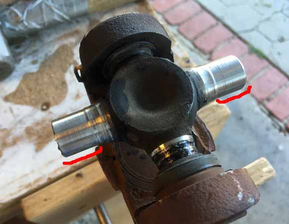
I didn't really test the old u-joints before I took the fire wrench to them. At 146k mi it scarcely mattered, bound to be wear. But I did notice as I set the transmission yoke up for its sacrifice to Pele just how amazingly worn the U-joint shafts were in the needle bearing contact area (highlighted in red)

ujoints06.jpg


Then it was on with the show.

ujoints10.jpg
ujoints11.jpg


Rear drive shaft ready to re-install after the fuel pump is in.

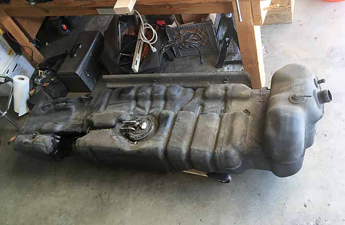
Fuel tank removal probably commences tomorrow after morning classes. I've been scudding around the last couple trips with the 'Low Fuel' lamp lit. So the tank shouldn't have much spam innit. I could probably get away with just tipping the end of the tank down, but I want to finish the tank plate prototyping so will probably remove it entirely. Depends how much of a PITA the plumbing is.
 

rayra

Expedition Leader
'The Eagle Has Landed'

fuelpump005.jpg


lunch break. Then it's:
tape up the various fittings / inlets
blast the grit and grime off the tank.
tip and pour off the remaining gas into a bucket / fuel jug. guesstimating about 2gal remain
do some messing around with the tank skin template pressboard prototype. and taking some measurements and photos of the saddle strap areas.
remove and replace the fuel pump
reinstall the tank, put ~7gal in it.
re-install the drive shaft and grease that rear joint fully.
Fire it up and take it off the 'hoist'.
test drive!

fuelpump002.jpg

fuelpump003.jpg

fuelpump004.jpg


18yrs+ those fuel tank hoses were on. Came right off without trouble. rubber on HDPE. And this Sub was Hecho en Mehico and has lived all its life in SoCal. Zero corrosion issues.
Little bit of struggle disconnecting a few lines, but I had the right hose release tools and once the tank was tilted for access just had to free the two primary hoses from the tank mounts and scoot the tank forward just a little to get some slack on the jaws of the 3/8" line coupling so I could get them spread with the tool and free the line.

The tank shield on the side facing the driveshaft is a flimsy arrangement. It's only rigid when the saddle clamps bind it's bottom edge. The plate otherwise floats on 4-5 studs protruding from the tank plastic, kept on with spring-steel discs pressed onto the studs. I'll take some pics later today while I'm messing with the tank skin idea.
 

Forum statistics

Threads
188,334
Messages
2,905,616
Members
229,959
Latest member
bdpkauai
Top