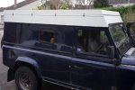
Making a ifting roof on a 110

wuntenn

Adventurer
Aye it's taking shape!

The lifting portion has now got fairly heavy - not ridiculously so, but sufficiently that I can't easily shift it on my own. I need to get assistance to move it around and turn it, so that slows me down a bit.

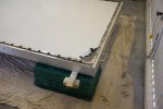
Currently doing the pre-priming cleaning up. I"m putting some filler on the front and rear overlap joints where the thin roof alloy overlaps the thicker alloy frame, just to make it a wee bit more 'clean' looking. The sides will eventually be covered by the roof-rack assembly so should not be visible. Once I get a mildish day I can prime and topcoat it.

My problem then is actually assembling it!

I'll need four people to get the lifting section onto the top of the lower perimeter frame. Once its there a friend has offered me a barn to use for a day or two - I can put a pulley over a beam and hoist the end of the lifting section up and over far enough to reveal the hinge end so I can seal and screw the hinge down. That's a pretty crucial part as it needs doing properly to prevent leaks, and I need it securely supported so it doesn't fall or crush anyone in the process. Its not hugely heavy, but its 9' long and a few pounds on the end of a 9' lever exerts a considerable amount of force.

Don't want to see several months of work trashed courtesy of uncontrolled gravitational acceleration (and subsequent deceleration!)
 

redneck44

Adventurer
Hi
I've been watching this thread with interest, very nice work.
You have just mentioned weight, how does this conversion fit with the 75kg max roof (not roof rack) load recommended by LR, AIUI the 75kg limit is to do with vehicle stability rather than strength. I only ask as I'm probably going to do a pop top on my 110.
 

wuntenn

Adventurer
Hi Red - my calculations bring the new lifting roof in at around 60-70kg - that's both the lower perimeter frame and the lifting section, which includes a very robust (yacht) hatch made out of alloy with 11mm perspex, and the to-be-fitted-later roof bars made very simply from alloy L section with a load of holes bored through it, bolted to the roof edges, and with a couple of alloy pipes across the width (and the ply sleeping platform that's up top also.) The roof section I'll remove from the existing roof (about 1/2 of it) is probably 8kgs or so, so that's a saving.

So I'm probably not anywhere near compromising vehicle stability.

Putting this into perspective - a conventional roof tent is between 45 and 90 kgs, depending on make and size, and that's without a roof rack to support it. Add a rack which will be at least 25kgs and the overall weight on top is between 70 and 125kgs.
 

redneck44

Adventurer
That sounds good on the weight.

I always cringe when seeing land rovers with monster roof racks with a ton of gear sat up there.
 

wuntenn

Adventurer
Aye, it's too easy to overdo it. I'm aiming to have my internals pretty lightweight too - the sleeping platform will be two 4mm ply sheets braced with 19mm square pine inside and a squirt of builders foam, which I'm aiming to be stronger and lighter than the same area of 19mm plywood. And no MDF is going to be used in the various cupboards and sink/cooker units either - its far too heavy and a few sheets of that is way more weight than necessary. 4-6mm ply and some thin pine is all thats needed. If laminated wood is good enough to build car chassis and make boats that can last a lifetime then it'll do for a LandRover interior!
 
If laminated wood is good enough to build car chassis and make boats that can last a lifetime then it'll do for a LandRover interior!

The key to that statement is what adhesive is used in the plywood. Ie marine grade as opposed to regular ply from a home supply place.
 

wuntenn

Adventurer
I agree with you re the ability to withstand water. However I wasn't particularly referring to the waterproof qualities rather the structural integrity.

My experience is that the adhesive is of less importance than the design and construction (although the adhesive IS very important!). I've seen marine ply disasters that have failed from a structural POV because the builder thought the stuff had magical properties. I've seen some beautiful work made from birch ply which is not *waterproof* but which is pretty strong and had been built properly and well sealed and has lasted.

Mind you.....*thinking*...........Land Rover....leaks......hmm...........boatbuilding techniques..........*thinks*..........yes you might be right - marine grade to prevent my leaky 110 rotting from the inside out might be a fine idea! :)
 

wuntenn

Adventurer
Still waiting to try to get the lifting top painted. Been a bit rainy so not much joy.

But I ordered the gas struts yesterday and they arrived today. Fantastic service from the suppliers Struts Direct (I have no connection with them otherwise). They have an online calculator and lots of helpful descriptions of how the struts work and how to establish what you need. I used their free design service - enter the length, width, depth of the base and lid, and the location of hinge, and weight to be lifted, and they work out the correct dimensions and fitting location and send you the following very helpful diagram.

struts.jpg

My requirement is for a flat-surface-fixing for the top (tube end) and a vertical-side-fixing for the lower (rod) end. Each strut end can accept a variety of fittings and there is a good range so you can pick the appropriate fixing for individual need (or have one made to suit for special requirements). I've got the steel eye at top, with a bolt-through fitting to the flat plate (which is then screwed up into the wood on my roof). The bottom is a ball joint and my choice of side-fixing, which is so that I don't have to make any holes in the horizontal surface of the alloy lip which might be a leak point.

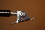
This is the top fitting (tube end) with the fixing plate attached.
strut-2.jpg

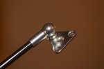
And this is the rod end (bottom) which will be bolted onto the side of the upstand.
strut-1.jpg


Here's the diagram showing how they will fit. Strut diameter (tube) is 18mm (and I have 25mm space). This is the SD02 type, 345mm long tube (giving a 'stroke' of 300mm) so the overall length open is 645mm. The struts will support up to 35kg each so plenty strong enough for my roof. The strut will only actuate beyond 12 degrees so it'll need a good push for that initial movement. The red bit is the lower fixing plate (as shown above) located on the side of the upstand (or 'verge' or whatever else you want to call it!), which will hopefully be a location that will prevent water entry. The canvas side fabric will of course be located behind this fixing plate - in other words the fabric sides will be fitted first and then the strut fixing plate bolted through the fabric and the alloy. I may need a small spacer between the fabric and plate to prevent chafing, but will have to see it operate to establish exactly how it will be finished.

strutloc.003.jpg
 
Last edited:

wuntenn

Adventurer
Today was painting the lifting section. My neighbour has allowed me to use his wider garage to do it in which was a relief as the weather's been a bit damp. We had to get it from my house to his so I made a small trolley with castors on it and we lifted it on and rolled it down the street last night in the dark - made a hell of a noise and got the street wondering what was afoot. The last bit is his gravel drive over which the trolley would not roll so we had to lift, and realised that it was not actually so heavy as we thought and was an easy carry.

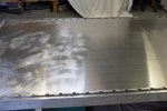
Anyway - peeling off the plastic protective sheet from the alloy.

spray-1.jpg


Roughing the surface up with wire wool.
spray-2.jpg


First coat of Acid Etch primer - 1.5 tins.
spray-3.jpg


Then top coat - 10 cans of white.
spray-5.jpg


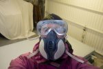
Me - mask, goggles, gloves, hood, and although I could not smell the heavy vapours in the mask (proper 3M jobbie) I could still feel the effect.
spray-4.jpg

So every new tin was taken outside to shake for two minutes, and it was mask off, deep breaths and then back in properly oxygenated. Its nasty nasty stuff that tinned paint and I dont really enjoy doing it. Its now drying and I may be able to lift it onto my LR roof in the next couple of days, depending on the number of neighbours I can draft in to help lift it.
 

wuntenn

Adventurer
Well it's painted and on the LR roof! Not sealed and bolted, simply sat there. My neighbour and I managed to lift it on on Sunday morning. Bit of a pain because it snowed, then rained then froze just before we got it on the roof so there was a good coat of ice on the roof when it went on. Then it snowed again so there was snow on the new roof as well! Ah the joys of driveway diy!

seal-5.jpg

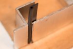
One problem I knew I'd have to overcome is that because I've had to split the welds on the drivers side lifting section the additional heating when it was rewelded has caused a slight 'banana' in the long inverted L section that forms the sides. You can see it at the left and right ends of the join. It looks worse than it is - it's about 2mm of a gap. I was a bit concerned about this so figured I could ameliorate this when I fit the seals. I say 'fit the seals' as if I knew what I was going to use, but I didn't and am deciding now!

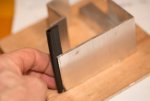
What I reckon might work is a length of P section rubber fitted into the join.

seal-3.jpg

You can see it in the cross-section model I've been using, below:

seal-1.jpg

It can be glued onto the back of the alloy sides of the lifting lid, and the thickness of the 'bulb' is less than 3mm so wont extend beyond the face of the alloy so should not interfere with the clips that pull/hold the lid down.

seal-2.jpg

The bulb seal is about 6mm and will deform to about 3mm under pressure which should be more than enough to accommodate the slight joint gap difference at each end of the side. Now of course fitting this P section on the two sides and rear will raise the roof by a few mm which I'll have to take into account in the front at the hinge area. But that's an advantage because it now gives me a few mm gap I need to fill and can use a rubber strip which will make a very good seal when squished and bolted down under both the lower hinge leaf, and above the upper hinge leaf. I'm considering using something like this:

AT1993big.jpg

Which I can put above the top leaf with the flap of the L hanging out and pointing down to cover the ball of the hinge and stop water and dust from getting blown in. I can of course also use a simple flap of rubber that goes under both hinge leaf and forms a U around the hinge ball. Will need to do some testing on the actual roof and see how much the P section deforms and what the actual height it raises the roof is (as defined by width of the gap at the hinge).
 

Attachments

  • seal-4.jpg
    seal-4.jpg
    56.4 KB · Views: 55
Last edited:

wuntenn

Adventurer
Cheers Arjan.

There may be a change of seal plan. I'm now considering a simpler method, which is a composite of two neoprene rubbers - one is a 1mm thick section of solid neoprene rubber and the other an expanded neoprene about 4-5mm thick. These will be bonded together by the manufacturer, and have an adhesive backing with peel-off tape. The idea is that this will be 30mm wide and stuck down to the lower (horizontal) section of the fixed portion of the new roof. The solid neoprene gives robustness, and will withstand the wear and pressure of the roof coming down onto it, whilst the expanded stuff deforms underneath and allows it to accommodate the slight 'banana' shape in the section. It's substantially cheaper than the P section too, as well as easier to fit. This will also act as an insulator and prevent condensation, which as I've watched over the last few days will freeze solid.
 

Forum statistics

Threads
188,347
Messages
2,905,926
Members
229,959
Latest member
bdpkauai
Top