You are using an out of date browser. It may not display this or other websites correctly.
You should upgrade or use an alternative browser.
You should upgrade or use an alternative browser.
Overland Sprinter Build
- Thread starter luthj
- Start date
llamalander
Well-known member
I was looking at various solenoid options for water and came across power actuated ball valves, which only draw energy when actually moving, but can still hold a position while a switch is open, then revert when power is removed. The catch is it can take a few seconds to open or close, but they don't seem to heat up like other solenoids I've used
(I'm using the 2-wire auto return version, but this is basically the same)
(I'm using the 2-wire auto return version, but this is basically the same)
Alloy
Well-known member
Think the top (blue) are on/off actuators and the bottom (red) is flow control.Waiting for lunch to cook, and looking ahead to a few items that need resolved prior to winter. On of these is freeze control for the gray water tank and lines. Another (farther down the road) is heating the engine and possibly fuel tank/lines.
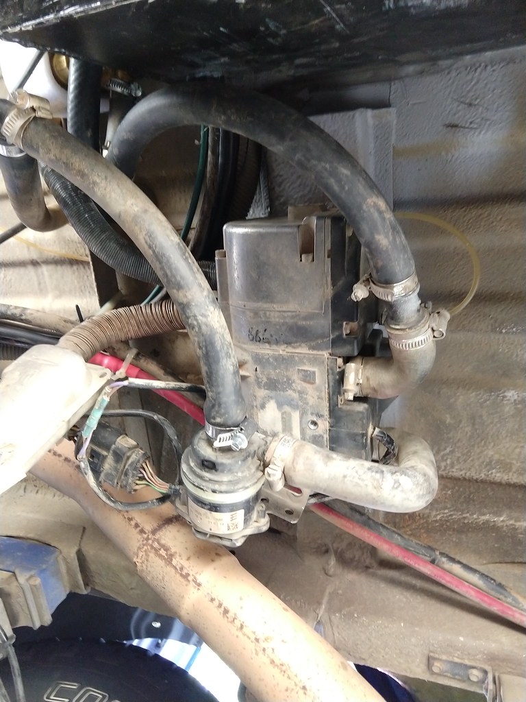
Since I will need to relocated my hydronic heater due to the battery box install, I am considering a redesign.
-Isolate hydronic heating loop from engine, due to increased plumbing
-Install plate heat exchanger for preheating engine
-Plumb heating coil for gray (and eventually custom fuel tank)
-Plumb heating lines for drain hoses
-Design control unit which can run the pumps and heater to: Heat water tank from engine, heat engine from hydronic loop, and perform anti-freeze operation.
Doing some googling to see what options I have, I came across this floor heating manifold set. It looks like each circuit has a thermostatic valve on the return side. So I can adjust the temperature of each loop as needed. That would reduce heat loss to the tanks in warm weather. Its pretty big though. I am not sure what kind of flow resistance it would create either.
View attachment 604467
Thermostaic control is done with a balancing valve before the manifold.
The air vents (top right of each manifold) are prone to leaking.
Anton2k3
Adventurer
Great thread and build, long time reader here. So we have a 2012 sprinter 516 4x4, and I have installed pretty much exactly what you are looking at. We have a heat exchanger in the hydronic loop which is also connected to the engine. As you say, this allows both preheat of the engine, and for the engine to heat the hot water calorifier and run the external fan matrix heaters (when required) when driving. We have also used exactly the same manifold you are looking at, but we run it for it’s intended purpose, under floor heating. The one we have for sure doesn’t have thermostatic valves. It wouldn’t make sense, heating manifolds are usually installed outside of the rooms they heat. Thermostatic valves work on ambient temperature. The ones on ours are simply open/close valves. The flow can be adjusted using the flow globes (they turn). Otherwise, great idea! For our tank heating I’m just going to T straight off hydronic coolant circuit under the van, with a valve to balance and adjust heating...simple I find is better..less stuff to mount
luthj
Engineer In Residence
Yeah, tradeoffs. Trying to balance, size, weight, complexity, and cost. I like the ball valves, they are just a bit big.
I might be able to work with a manual shutoff to switch between winter and summer mode. Not as user friendly as a dynamic control scheme, but definitely smaller and cheaper.
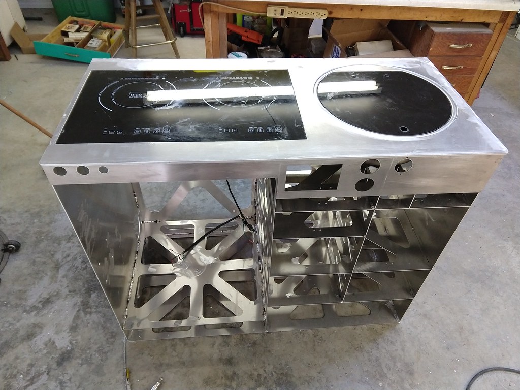
Galley is mostly together, Just need to weld up the bins. I am considering a direct to metal clear for the top and front face. And grey epoxy for the rest of the surfaces. Bins are undecided, but will probably be painted to match whatever I do to the fridge door.


Alloy
Well-known member
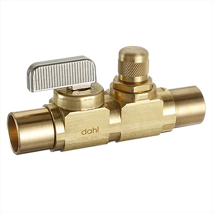
FYI...Dahl Mini ball valves
 www.dahlvalve.com
Talk to the guys doing alum wheel repairs for the best alum clear coat

mini-ball Balancing Valves 121BAL-13-13
dahl product #121BAL-13-13 is suitable for Heating, Hydronic Heating and Radiant Floor Heating applications.
Talk to the guys doing alum wheel repairs for the best alum clear coat
luthj
Engineer In Residence
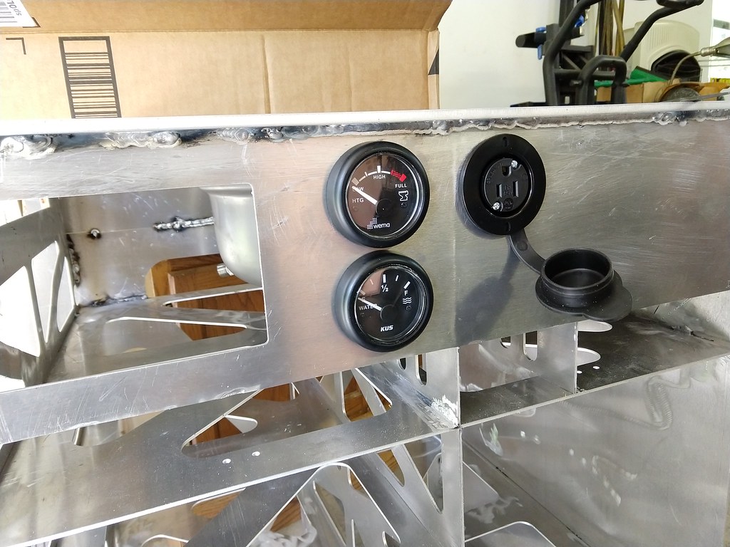
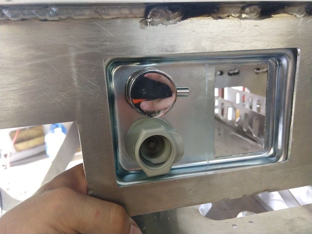
Still working on the galley. Getting close to paint. Need to buff the top, and brush the visible welds. When I was removing the cooktop I got the corn cockeyed on some old silicone. Put a 3" crack in the top... I filled it with some windshield repair resin. However it looks like the top might be opaque to UV. I will leave it in the sun all day, and see if it holds.




luthj
Engineer In Residence
Got the shower curtain installed. Jen sourced some stainless fixture pins. These are positive retention with a release button. The curtain is a standard length XPLR Outfitters model. On the bottom there are 4 15lb magnet catches. I will sew one side to the curtain, and bond the other to the pan edge.


luthj
Engineer In Residence
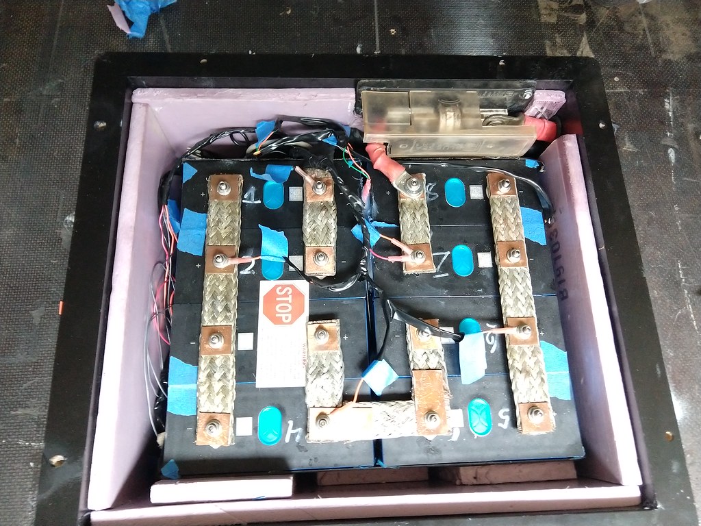
Battery pack has been commissioned and is working fine. I will do a capacity test later this week, and setup the alternator charging.
Gray tank i installed, and awaiting plumbing. I insulated where possible, but may add some more down the road. I may change the filler wire next time around. I had about 8 leaks when I tested it. When I patched the leaks, I was getting thermal stress cracks at the start/termination of the weld patches. Pre heating may have helped with them as well.
 [/url
[/url
[url=https://flic.kr/p/2jB45Zm]

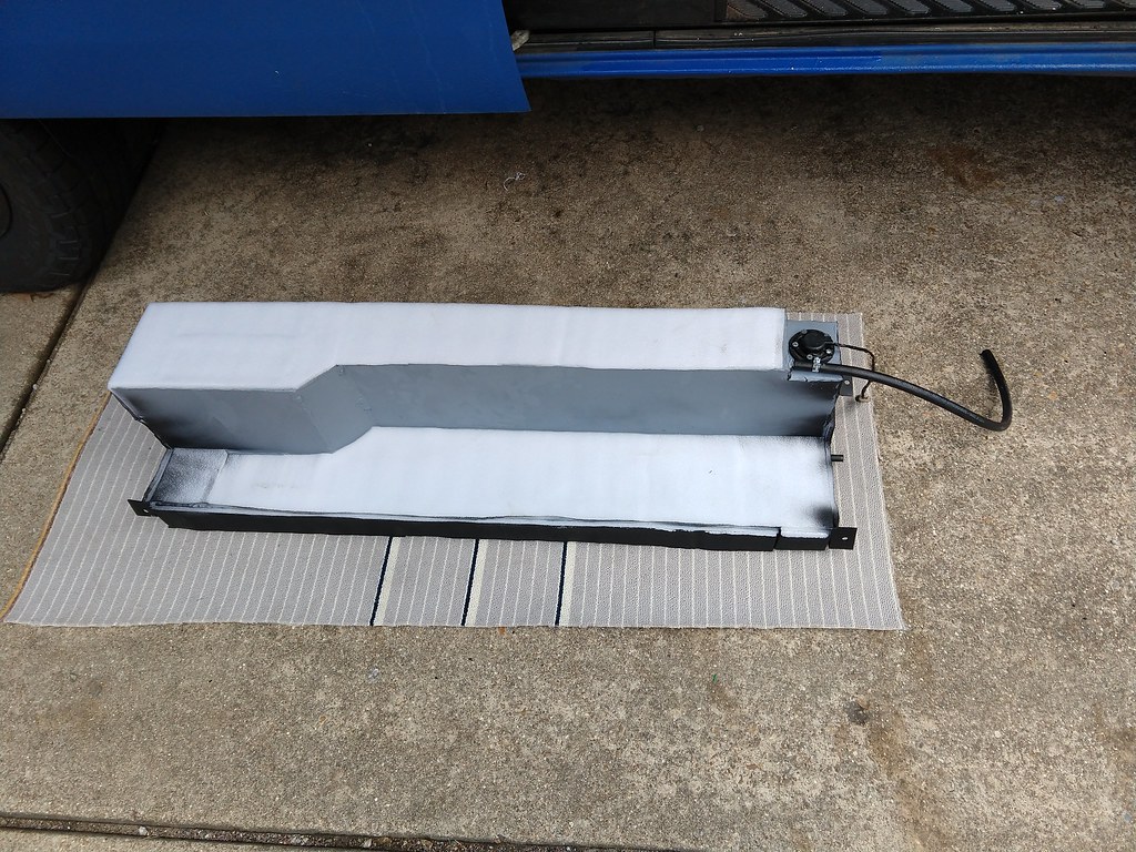
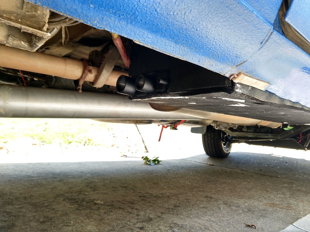

Gray tank i installed, and awaiting plumbing. I insulated where possible, but may add some more down the road. I may change the filler wire next time around. I had about 8 leaks when I tested it. When I patched the leaks, I was getting thermal stress cracks at the start/termination of the weld patches. Pre heating may have helped with them as well.
 [/url
[/url[url=https://flic.kr/p/2jB45Zm]


luthj
Engineer In Residence
Galley is painted, and electrical/plumbing have been fitted, I will get some photos up tomorrow. I have the main plumbing runs for the drains worked out. Just need to make a bracket to support the drain valve and camlock for the hose.
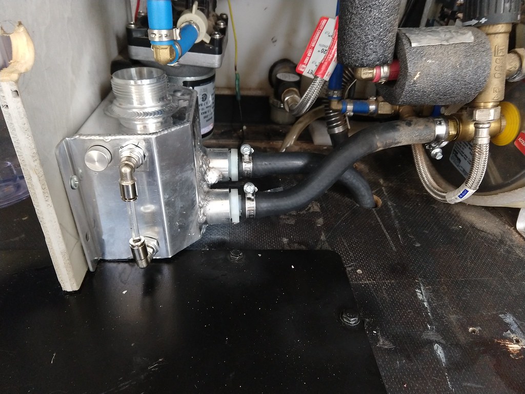
Planning forward to rebuild the hydronic system, and heating for the underbody lines. I think the easiest method is to isolate from the engine via a plate heat exchanger. I can locate one near the firewall below the brake booster. Then I can run the hydronic system at ambient pressure. A flow through reservoir in the mechanical cabinet (in series with water heater/main loop) should be doable.

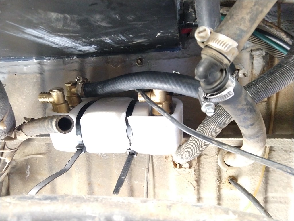
Under the van I can located a manifold pair with shutoff valves. Coolant feeds will be to the Gray tank, drain line feeds, and eventually the fuel tank/lines. I think I can use the grey tank heating loop return to heat the floor under the show pan, and the drain area. Both for comfort and freeze prevention when showering. I am going to need a bunch of different insulation styles, but I think a system without electric valves will be the most reliable. I will waste some heat of course, but with there being a couple gallons of coolant, plus the heat storage in the water heater (its in the main loop), cycle times should be reasonable. The goal is to calibrate the flow to keep the lines/tank above freezing, while the main loop cycles between 120F and 165F. Which lets me use the built in output control (800W or 5kw) of the hydronic heater. So I can just use a digital thermostat with a temp probe on the tanks/lines set for around 40F. Depending on how it works out, I may need a small circulation pump.
Now how the antifreeze lines are plumbed. I am leaning towards them having their own circulation pump, with a hydraulic separator between both (a double ended manifold will work). That way I don't need to shut all the valves when heat isn't needed in that loop. Instead the vales will be for flow control/calibration in each loop.

Planning forward to rebuild the hydronic system, and heating for the underbody lines. I think the easiest method is to isolate from the engine via a plate heat exchanger. I can locate one near the firewall below the brake booster. Then I can run the hydronic system at ambient pressure. A flow through reservoir in the mechanical cabinet (in series with water heater/main loop) should be doable.

Under the van I can located a manifold pair with shutoff valves. Coolant feeds will be to the Gray tank, drain line feeds, and eventually the fuel tank/lines. I think I can use the grey tank heating loop return to heat the floor under the show pan, and the drain area. Both for comfort and freeze prevention when showering. I am going to need a bunch of different insulation styles, but I think a system without electric valves will be the most reliable. I will waste some heat of course, but with there being a couple gallons of coolant, plus the heat storage in the water heater (its in the main loop), cycle times should be reasonable. The goal is to calibrate the flow to keep the lines/tank above freezing, while the main loop cycles between 120F and 165F. Which lets me use the built in output control (800W or 5kw) of the hydronic heater. So I can just use a digital thermostat with a temp probe on the tanks/lines set for around 40F. Depending on how it works out, I may need a small circulation pump.
Now how the antifreeze lines are plumbed. I am leaning towards them having their own circulation pump, with a hydraulic separator between both (a double ended manifold will work). That way I don't need to shut all the valves when heat isn't needed in that loop. Instead the vales will be for flow control/calibration in each loop.

luthj
Engineer In Residence
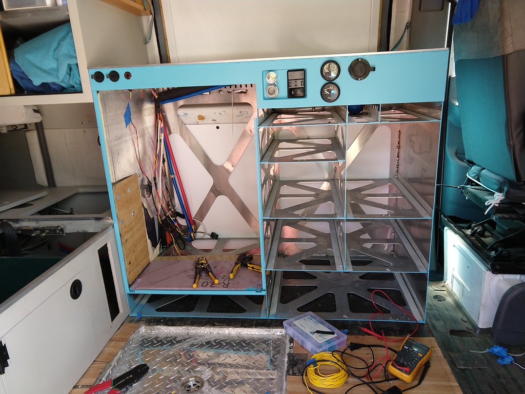
Galley is installed, though I need to finish the water and electrical connections. Should be pretty easy.
 IMG_20200903_115825689
 IMG_20200907_094331629
Ended up directional sanding the top, and using a clear urethane.
 IMG_20200902_162427165
 IMG_20200907_123548150 b
I am slowly filling the area around the windows with XPS foam.
 IMG_20200907_152310982_HDR
Here is a preview of the gray tank plumbing. I should have room to run a 3/8 heating hose, and wrap with insulation.
 IMG_20200905_122034282
 IMG_20200903_115825689
  IMG_20200907_094331629
Ended up directional sanding the top, and using a clear urethane.
 IMG_20200902_162427165
  IMG_20200907_123548150 b
I am slowly filling the area around the windows with XPS foam.
 IMG_20200907_152310982_HDR
Here is a preview of the gray tank plumbing. I should have room to run a 3/8 heating hose, and wrap with insulation.
 IMG_20200905_122034282
luthj
Engineer In Residence
Making steady progress. Should be wrapped up for the season this week.


Filling the area around the new windows with XPS foam.


Most of the new hydronic plumbing for stage 1 is installed. However I am getting air lock in one loop, so I need to move the pump. Stage 2 will involve antifreeze loops for the underbody water links and gray tank. I will need to order some components, and take care of that in november sometime.
The Fiamma awning crapped out on us. The gearbox started slipping. There is a 90 degree ring and pinion gear in this center gearbox. It allows the manual crank to drive the shaft. However it also counter holds the casing of the planetary reduction for the electric drive. No one, not even Fiamma direct, sells this gearbox separate from the motor assembly ($400+). Whats interesting is that Fiamma knows it was a design issue, Pleasrure Way RVs was forced to do a recall, as this gearbox failing can cause the awning to deploy when driving down the road. So there is an upgraded gearbox. It seems the case rivets on the casing stretching is the primary cause the gear stripping. Since we don't really use the manual crank, I opted to put a #10 sheetmetal screw through the case into the ring gear. This fixes the gear, letting the electric motor do its thing.


Filling the area around the new windows with XPS foam.


Most of the new hydronic plumbing for stage 1 is installed. However I am getting air lock in one loop, so I need to move the pump. Stage 2 will involve antifreeze loops for the underbody water links and gray tank. I will need to order some components, and take care of that in november sometime.


The Fiamma awning crapped out on us. The gearbox started slipping. There is a 90 degree ring and pinion gear in this center gearbox. It allows the manual crank to drive the shaft. However it also counter holds the casing of the planetary reduction for the electric drive. No one, not even Fiamma direct, sells this gearbox separate from the motor assembly ($400+). Whats interesting is that Fiamma knows it was a design issue, Pleasrure Way RVs was forced to do a recall, as this gearbox failing can cause the awning to deploy when driving down the road. So there is an upgraded gearbox. It seems the case rivets on the casing stretching is the primary cause the gear stripping. Since we don't really use the manual crank, I opted to put a #10 sheetmetal screw through the case into the ring gear. This fixes the gear, letting the electric motor do its thing.

luthj
Engineer In Residence
Working on finishing up modifications for the winter. Going to do some insulation and related to keep condensation down. Maybe install a second plastic pane in the rear window.
Working on the antifreeze for the underbody water stuff. I have a pile of parts I need to turn into a project. Arduino, relay board, temp probes, wire, switches etc. For the exterior bit I have a 3/8" output solar water heater pump, 3/8" ID heater hose, and a bunch of coolant fittings in various sizes. The plan is to run 3/8" hose along the water lines, and connect to the heating channel in the gray tank. I will also glue a loop of heater hose to the bottom of the shower pan area, and then insulated (no cold feet!). From there the loop will tie into the main hydronic loop with some tees.
If I set it up properly, I can use the water heater as a thermal reservoir, so the hydronic heater will only need to run a few times a day even in very cold weather.
The temp probes will be;
engine
water heater
antifreeze loop
ambient
This will allow me to intermittently run the pumps to keep everything above freezing, and run the coolant heater when needed. I can also program logic to run the pumps when the engine is running for free heat, and to heat the water for showers. When its above freezing ambient, the system will just sleep. I will need a few switches for manual control (wanting to take a shower, preheat engine etc). And some LEDS for system status. The code should be pretty simple, but I probably need to include some error checking, a status LED, and failsafe operation though.
Similar threads
- Replies
- 1
- Views
- 419
- Replies
- 12
- Views
- 2K
- Replies
- 0
- Views
- 816
- Replies
- 3
- Views
- 574

