Doug, I'm not sure what I'm proposing. My mind says it can work, but I haven't wrapped myself around it well enough to explain it. If that makes any sense.
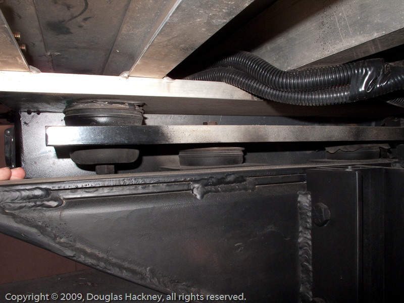
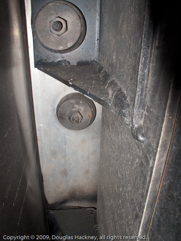
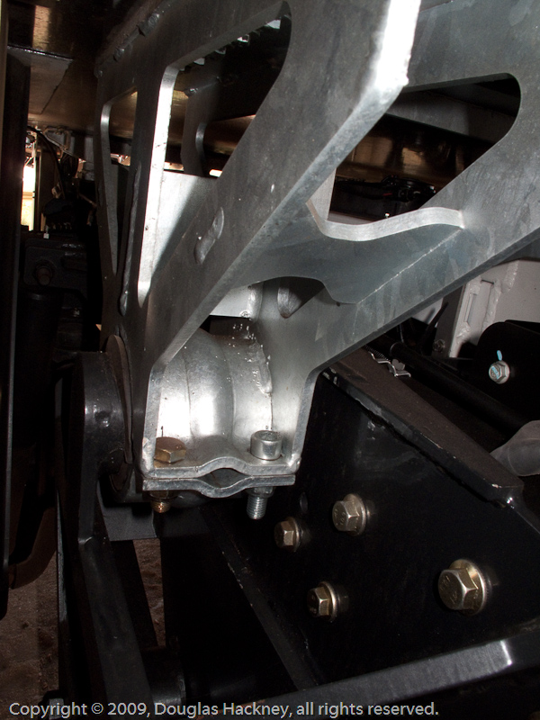
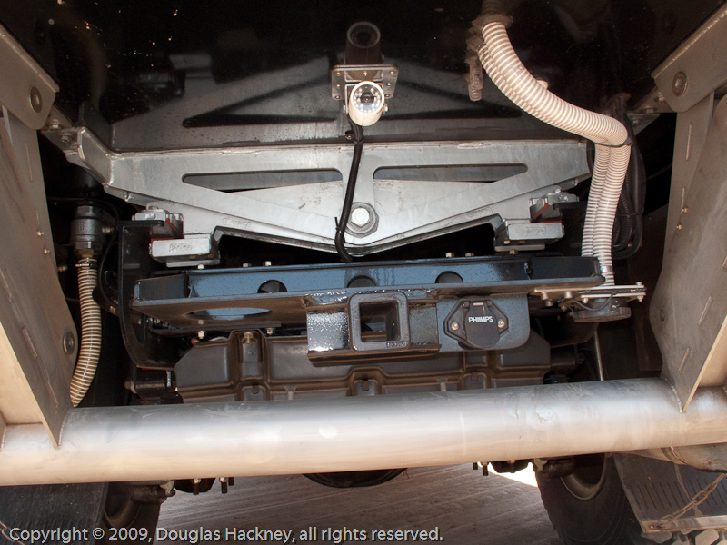
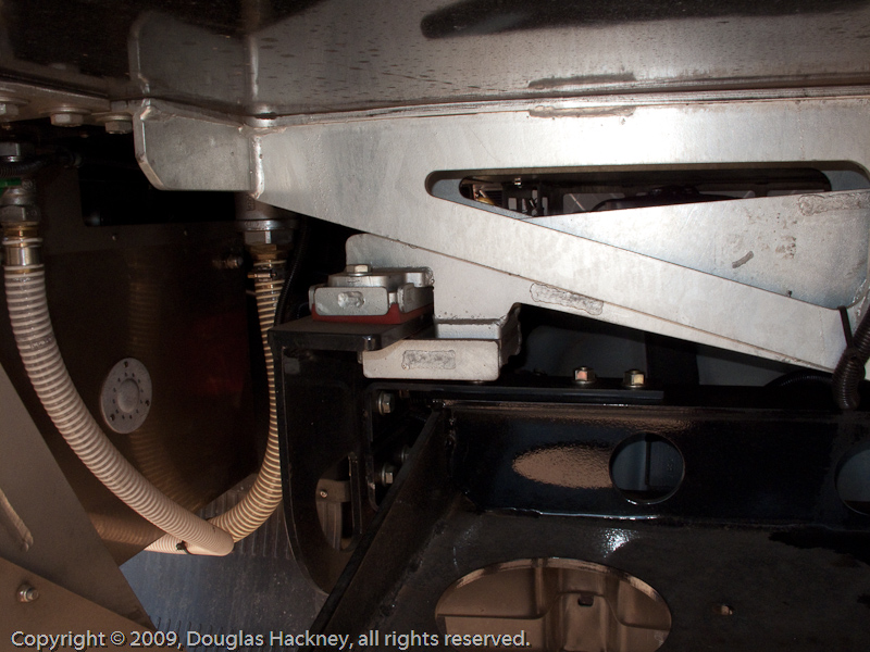
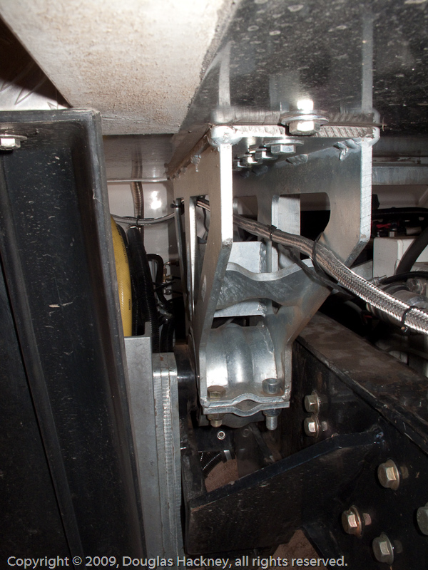
What I'm seeing is that there is a central pivot, like current practice in a 'diamond' mount, but instead of the end mounting points it would have periodic shackles placed along the length of each frame rail. I can see that the exact geometry of those shackles and their pivot points would make or break the concept. What I've not resolved is what that geometry might need to be.
Alan, do you have any postable pictures of what you built?

")