pivoting frames and mounting campers

IdaSHO

IDACAMPER
Pivoting builds that have used shocks? I haven't seen any except for Idasho's, which was not optimized for it. You want high damping low travel shocks (if you are space limited like mine), mounted pretty much vertical and outboard. I did some searching and found some old corvette rear shocks that seemed like they'd be decent... for my build on a pickup.

I thought the major issue was the rear end shifting back and forth and juddering over irregularities or sudden steering inputs. A slow lean would not bother me... just slow down.

To be clear. The shocks that my setup runs is primarily to reduce the ‘wobble’ the rear of bed sees when running empty. Which it has eliminated 100% For the most part, it is a sheetmetal framed bed, so it is anything but ridged. The camper itself provides a considerably amount of rigidity that allows the pivoting frame to perform as intended.

With regards to shocks and road manners, it should slow movement of the rear during maneuvers, but by how much? Its likely not even discernible.

When designing the bed I did also implement points that would allow me to fix the rear pivot if needed, with nothing more than ratchet straps. Though Ive never seen the need in real world. I had considered the air bags as shown above, but I was holding out to see if it would even be applicable. I dont think the road manners we have fully loaded warrant any such setup. It does great. The only change I have planned for the rear is a custom set of leafs, to reduce my dependency upon the bags.
 

rruff

Explorer
I dont think the road manners we have fully loaded warrant any such setup. It does great.

That's good to hear. My setup will be a similar 3 point, only the rear "pivot" will be fairly soft urethane cab mounts on the centerline. Front mounts will be hard urethane. If I think shocks are warranted they should be easy to add... the corvette shocks are pretty short.
 

Christian

Adventurer
Christian,. Maybe I misunderstand your illustration. You plan to support the cab / box weight with two lord's in the front and 2 air bags in the rear?.. I do not think that is a good strategy from the chassis perspective. The watts however nice has only the function to keep the box aligned but does not carry weight thru to the frame.. our 404 has supports about every three to four feet.. the rigid spine that runs thru just above the pivot points can twist but also helps the frame strength wise. The sub frame spine is not subjected to twist stresses from the road surface but it is going to be extended and compressed by inertia stresses when you go thru bumps on the road . Basically the chassis / frame becomes from 2 parallel beams three parallel beams with the third located above the original two. So a lot stronger from a bending perspective and of course not from a twisting perspective.
If you really want to use bags that I would put those closer to the rear axle and put the watts in the rear.

Good luck

Johan

Hi Johan,

A central spine? Like the chassis on a Tatra? I can't do that, it would interfere with the chassis, or be too high. The airbags and the Watts linkage are at the rear. I plan on building a very light and stiff box in a monocoque design, so I'm pretty sure it will work. I have aked a few engineers and truck builders, and they see no real problems in my design. But I hope time will tell!
 

Christian

Adventurer
To be clear. The shocks that my setup runs is primarily to reduce the ‘wobble’ the rear of bed sees when running empty. Which it has eliminated 100% For the most part, it is a sheetmetal framed bed, so it is anything but ridged. The camper itself provides a considerably amount of rigidity that allows the pivoting frame to perform as intended.

With regards to shocks and road manners, it should slow movement of the rear during maneuvers, but by how much? Its likely not even discernible.

When designing the bed I did also implement points that would allow me to fix the rear pivot if needed, with nothing more than ratchet straps. Though Ive never seen the need in real world. I had considered the air bags as shown above, but I was holding out to see if it would even be applicable. I dont think the road manners we have fully loaded warrant any such setup. It does great. The only change I have planned for the rear is a custom set of leafs, to reduce my dependency upon the bags.

The airbags in my design are not an afterthought or bandaid to eliminate body roll, but a part of an entire system, and the solution to more than one challenge.

Vibration control was adamant to me, my truck has leaf springs, and going down gravel roads with corrugations or potholes transfers directly through the chassis. And according to more experienced travellers than me, that wears heavily on the box.
Having box and cab as one only makes it worse.

So as Rruff I looked at implementing softer poly or rubber mounts somewhere. But wanting to have the pivot in the back made me want to make sure I could control body roll, as we discussed above.
Having the airbags there made me want to use them in the vibration isolation, which meant I needed some vertical give in the pivot mount, and the best solution was the Watts linkage.

After a lot of sketches and design changes that lead me to incorporate both issues in one solution, actually having a secondary suspension system between the chassis and subframe.
 

IdaSHO

IDACAMPER
For what its worth, our camper has more than 75,000 miles on it, between two trucks, with nothing more than bush’d pivots of isolation. No worse for wear.

While isolation makes sense on paper, my real world experience shows that it simply isn't required. Your milage may vary. ?

Do you have any swaybars on your rig?
Our 2011 F250 has a factory front bar. Nothing in the rear. Suspension is stock, with Monomax shocks and rear leveling bags. ?
 

joeblack5

Active member
The " spine" I am talking about is the tube that connects the crossmember of the subframe..

My point is that it is bad practice to load your truck frame only at the beginning and end.
Lessons can be taken from the success of a frame and subframe bolted together with lots of detail on tapered end of the wooden or plastic frame spacers... All to avoid localized stresses. On this 404 unimog chassis you can see that the vertical weight / load is transferred to the frame about every meter.
Your truck frame might be different but many truck frames (Fuso) are tapered at the rear and are not able to carry all the load on the last part of the frame..
Again, maybe I misunderstand you drawing but I would be surprised that a PE would sign of on the load distribution.

Johan
 

Attachments

  • IMG_20211105_155704065.jpg
    IMG_20211105_155704065.jpg
    3.3 MB · Views: 53

Sitec

Adventurer
That sounds interesting! and you know the positives and the downsides. I have actually thought about this a lot through several years. I have read just about all the discussions, theories and real-world experience. I started a project on a Volvo TGB just because the frame is rigid. but two kids later, it was too small even before it was finished.

So we bought a Mercedes LAF 1113B, much larger, but with a flexible chassis. Ok, it's not that big, approx. 7.5m/24.5ft. So I want to make it a fully integrated, so we can utilize the cab space while camping. I know this goes againt all canon here, but that's what we want.

So I'm trying to design a subframe that´s a bit unusual:

Up front there will be two heavy LORD cab mounts, which will support the front weight and control the front both vertically and horizontally.
These will also keep the subframe and chassis in alignment up front, so controls (gearshift, gas pedal etc.) will not be affected by movement.

Approx. above the rear axle there will be a Watts linkage which will control the rear side to side, but allow chassis flex and vertical displacement.

Behind the rear axle there will be an airbag on each side. These will support the weight of the subframe in the rear. On-road these will be inflated and controlled individually. Off-road they will be connected to allow air from one to go to the other. This way they will allow the chassis to flex.

I believe this should work, and have run FEA on the subframe. A bonus will be isolating the box from the chassis vibrations.

Please look it over and give me all your thoughts both positive and negative, as long as they are constructive!

PS: the yellow shadows are an interference block I have used to make sure I did not design anything that would interfere with the chassis while flexing...
TView attachment 585757View attachment 585758View attachment 585759View attachment 585760View attachment 585761View attachment 585762View attachment 585763

So, I've had some time to sit and read the latter part of this thread again, and your post. I have a few points that I can see might need slight adjustments. Firstly the LORD mounts. If you plan to have the large washer under the LORD mount (like on tractor cabs) so in the event of a mount failing, the inner part of the mount can never be pulled through and out of the outer part, then LORD mounts should work well. However, I wouldn't rely on only two. I'd look to 4 LORD's (two either side mounted no more than a meter apart) spreading the load of the front of the cab & Hab Box combo. The amount of chassis twist within a meter would be easily handled by 4 LORD's. I also agree with @joeblack5 in that it's not good having all the load at the front and rear of a chassis, so I'd be having the front pair of LORD's where you have them drawn, I'd have the second pair at the back of the cab, and I'd then have a second set of air bags mid way between the LORD's and the rear air bags (giving you 8 support points on the chassis rails). I'd also have two centrally mounted bump stops running in line with the center of your Watts Linkage that are located on the Hab Box subframe just above the two X members that run between the rear spring hangers. These would be set up so they are just touching the X Members but are there in case the air bags fail or drop over night.
 

Christian

Adventurer
The " spine" I am talking about is the tube that connects the crossmember of the subframe..

My point is that it is bad practice to load your truck frame only at the beginning and end.
Lessons can be taken from the success of a frame and subframe bolted together with lots of detail on tapered end of the wooden or plastic frame spacers... All to avoid localized stresses. On this 404 unimog chassis you can see that the vertical weight / load is transferred to the frame about every meter.
Your truck frame might be different but many truck frames (Fuso) are tapered at the rear and are not able to carry all the load on the last part of the frame..
Again, maybe I misunderstand you drawing but I would be surprised that a PE would sign of on the load distribution.

Johan

Hi Johan, thanks, now I get your point, and you are right, and I do plan on spreading the load a bit more in the back. But my truck has a load capacity of 6,5T, and I plan on a mx. of 2T, so it will be under a lot less stress than intended.
The frame on these are MUCH stronger than a Fuso!

So, I've had some time to sit and read the latter part of this thread again, and your post. I have a few points that I can see might need slight adjustments. Firstly the LORD mounts. If you plan to have the large washer under the LORD mount (like on tractor cabs) so in the event of a mount failing, the inner part of the mount can never be pulled through and out of the outer part, then LORD mounts should work well. However, I wouldn't rely on only two. I'd look to 4 LORD's (two either side mounted no more than a meter apart) spreading the load of the front of the cab & Hab Box combo. The amount of chassis twist within a meter would be easily handled by 4 LORD's. I also agree with @joeblack5 in that it's not good having all the load at the front and rear of a chassis, so I'd be having the front pair of LORD's where you have them drawn, I'd have the second pair at the back of the cab, and I'd then have a second set of air bags mid way between the LORD's and the rear air bags (giving you 8 support points on the chassis rails). I'd also have two centrally mounted bump stops running in line with the center of your Watts Linkage that are located on the Hab Box subframe just above the two X members that run between the rear spring hangers. These would be set up so they are just touching the X Members but are there in case the air bags fail or drop over night.

Thanks Sitec, good points. And of course I plan on "safetify" (LORD's expression) with big washers, just as I do on i.e. Landcruisers.
I have made one change, since the I uploaded the drawings. I got the advice to have some extra control on longitudal forces, so I've added a pair of Panhard bars up front, same size rubbers etc. as the links in the Watts linkage.
This also means I can refine the LORD mounts a bit, in regards to softness, when not relying only on these to control those forces. And that means your suggestion might be a good idea, 4 instead of 2.
The airbags I have chosen have internal bump stops and I have placed them so the bump stops makes sure the frames almost (but never) touches, if I loose air.

Having studied the body builders manual on dump trucks etc. they all have a subframe on chassis all the way back, but in a much smaller dimension than the chassis.
On dump trucks the pivot point is about a meter behind my Watts linkage point. When tipping, the added subframe can't spread the load along the chassis, and the forces right at the back of the chassis must be massive - let's say a 6,5T load, most of it, maybe 5T right at the rear of the chassis.
I my configuration I will have max. of 1T right over the rear spring hangers, so I'm not really worried.. (should I be?)
But additional airbags midpoint could also take some stress out of the subframe, so I'm not ruling them out!

Thank again, both of you!
 

Sitec

Adventurer
Yup, that all makes sense. You also plan to have a relatively low 'load' on your truck. Re tippers, they more often than not have the rear axle at the very rear, and only tip when stationary or moving slowly. They also often have short multi stage tip rams somewhere in the center. The long front mount rams are less common now. Sounds like you are all over it. Bump stops in the air bags makes a lot of sense. :)
 

4x4Canterman

New member
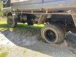
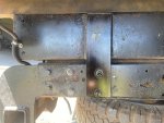
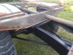
G’day all, interesting topic and great thread. I have a 97 FG 4x4 swb. I took some photos of it crossed up a bit to see if I need to fabricate a subframe with more compliance to twisting. It has a reasonably strong steel tray mounted rigidly at four points along each of the chassis rails. The fish plates and bolts are pretty decent. 3.6 x 2.3 tray size. Parked in this position I roughly measured 80mm height difference across the tray due to the twisting chassis. I reckon you could easily articulate this much in regular suburban environments. My local supermarket has a steeper entrance that you always approach on an angle. It’s just not practical to swing out into oncoming traffic and square up. I will most definitely be changing my subframe system before building my camper box. Cheers, Al
 

Attachments

  • 2327429C-F5C4-48BB-9B05-C3272F16123C.jpeg
    2327429C-F5C4-48BB-9B05-C3272F16123C.jpeg
    180.1 KB · Views: 59
  • 8895BB16-88DD-4BB3-964C-2846CCDAF0CF.jpeg
    8895BB16-88DD-4BB3-964C-2846CCDAF0CF.jpeg
    150.1 KB · Views: 60
  • 190E9515-816A-43F9-AD40-88C465CFA96A.jpeg
    190E9515-816A-43F9-AD40-88C465CFA96A.jpeg
    215.5 KB · Views: 58
  • 01E6B89C-44CF-4841-B7BF-4B235C1EA381.jpeg
    01E6B89C-44CF-4841-B7BF-4B235C1EA381.jpeg
    210.3 KB · Views: 47

rruff

Explorer
I suspect the flatbed was made to flex also, else it would have stiffened the frame a good amount.

Might be good to copy what Earthcruiser is doing. They use a combination of poly mounts and springs, shown in the video below. He is a member of ExPo (kcshoots I think) and has a thread here as well.


The Artisan

Adventurer
I suspect the flatbed was made to flex also, else it would have stiffened the frame a good amount.

Might be good to copy what Earthcruiser is doing. They use a combination of poly mounts and springs, shown in the video below. He is a member of ExPo (kcshoots I think) and has a thread here as well.

Why is the rear DS so short which causes such a steep angle?
Kevin
 

Forum statistics

Threads
188,154
Messages
2,902,876
Members
229,582
Latest member
JSKepler
Top