Rango.....1942 Willys MB

Metcalf

Expedition Leader
Well dang....two projects keeps me pretty busy....

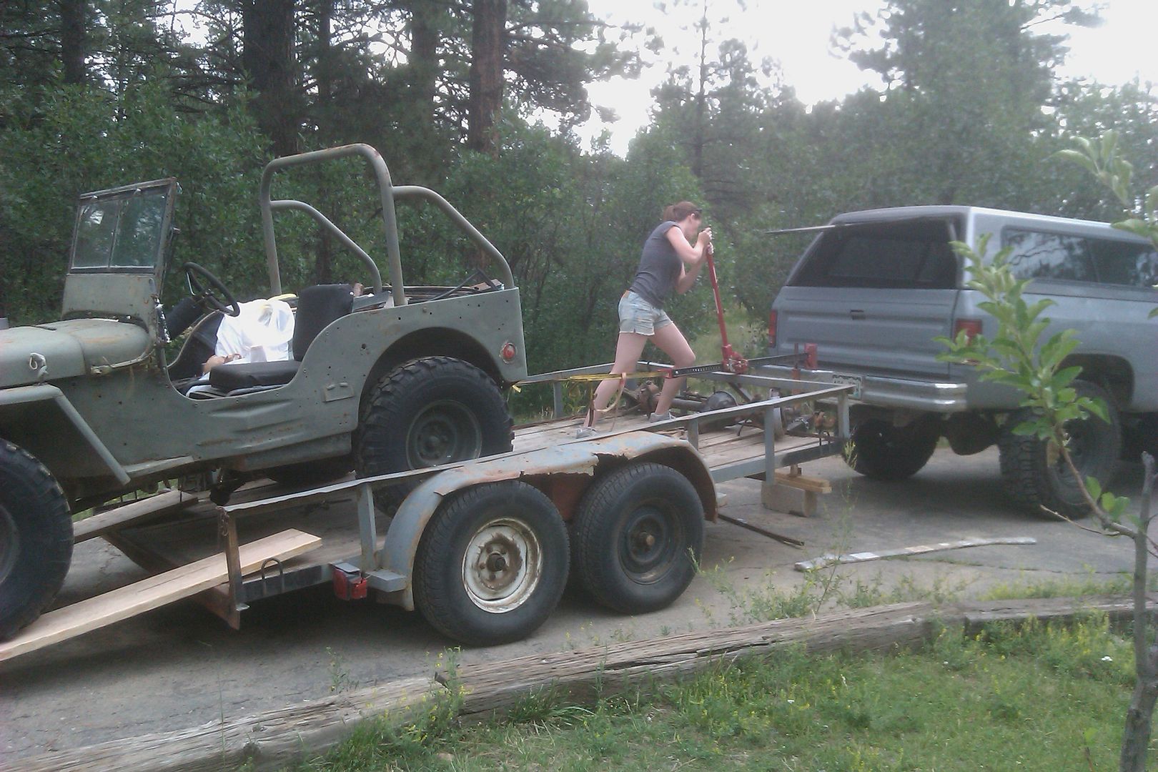
I pulled the transmission out of the Willys today to swap in the replacement. The current transmission (sm420) was in the vehicle when I bought it. Its always had some issues, but it lasted the 8 years or so. This spring it finally gave up. I heard a bang when I pulled it out of the snow this spring....

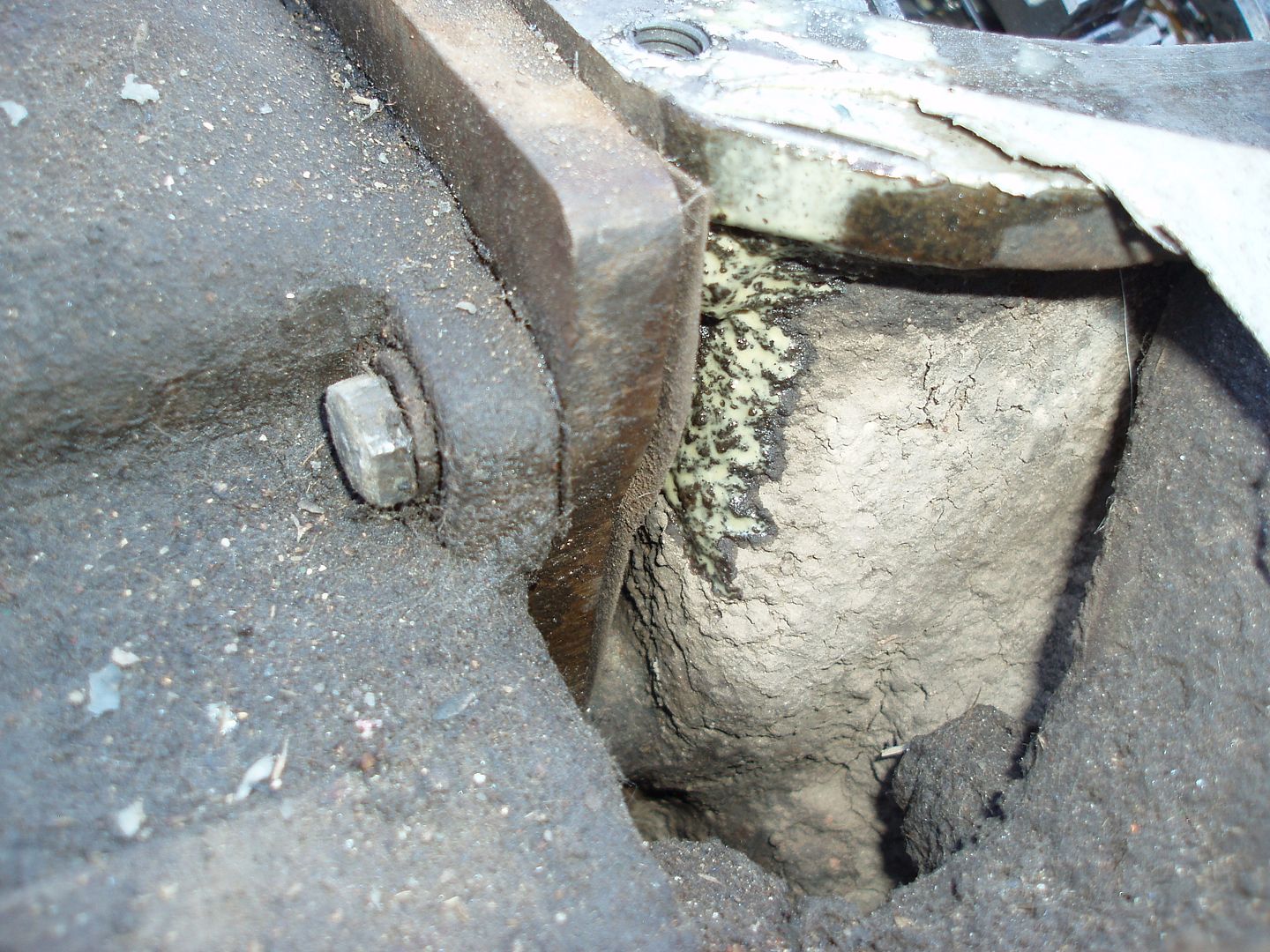
Getting the transmission out was fun....not. The install by the previous owner was TIGHT. The v-6 is a little close to the firewall and high in the chassis. This made getting the tranny out HARD. I ended up having to trim the tunnel a bit to get the top of the bell housing down and out. Getting it back together is going to be fun.

P1010228.jpg


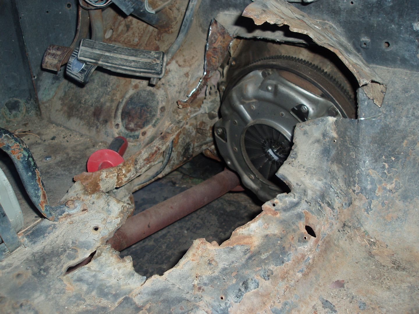
ouch. The tunnel was heavily modified by the previous owner. I would suspect that the engine/trans/t-case was installed without the body tub on the chassis. I should be able to weld everything back to where it was when I get it all back together.

P1010207.jpg


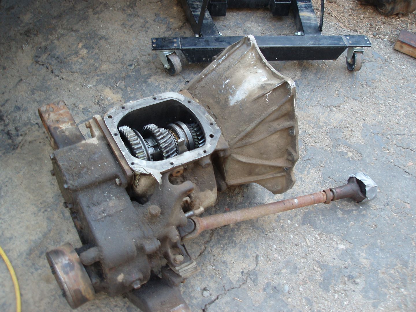
Here is the trans and t-case out of the jeep. Its sure compact. The 1/2" thick adapter is COMPACT for sure.

P1010209.jpg


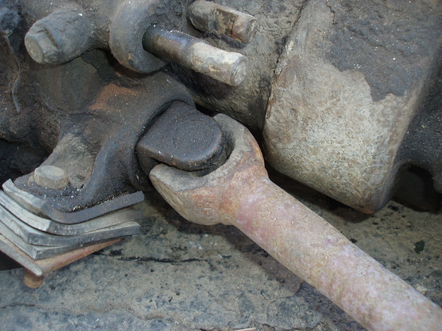
The front driveshaft uses a small style u-joint similar to the th400/d18 version. This is the only way the driveshaft u-joint can clear the transmission with the compact adapter.

P1010208-1.jpg


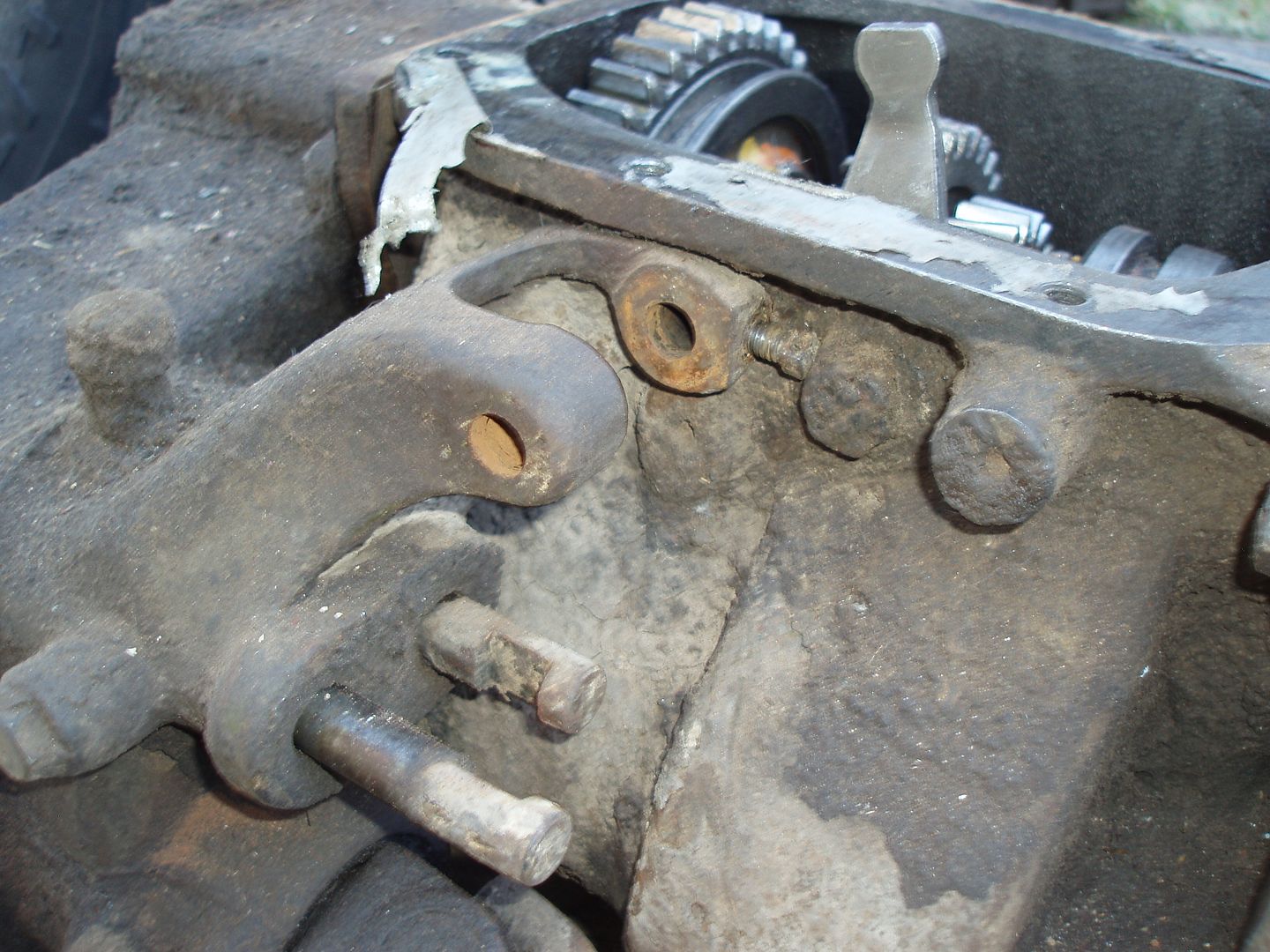
Here is the factory twin stick shifter snugged up against the transmission. This thing BARELY fits. There is a custom shaft for the shifters that has a set screw on the end. I'm amazed it all fits.

P1010211.jpg


P1010212.jpg


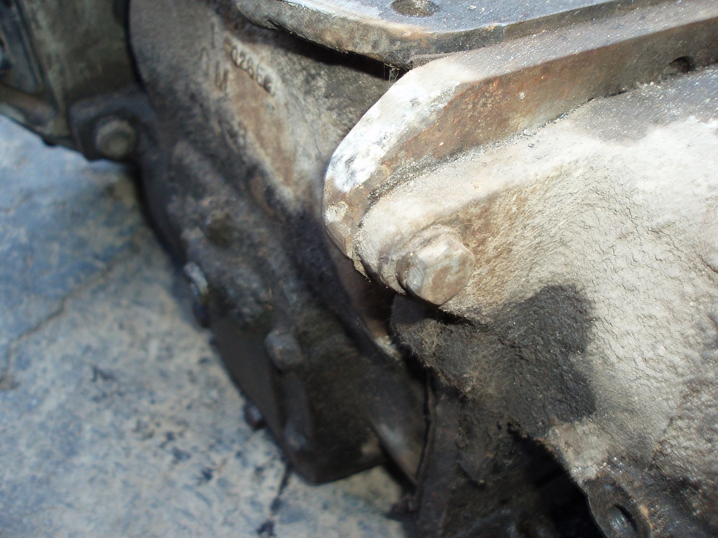
Here are some shots of the 1/2" thick adapter plate. Boy it makes things TIGHT! It does give me a nice long drive line though....

P1010214.jpg


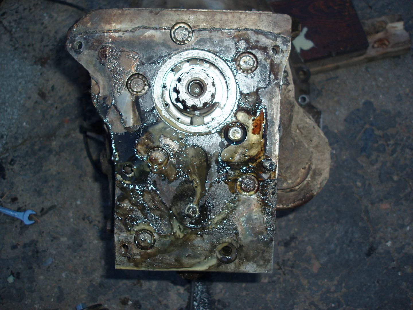
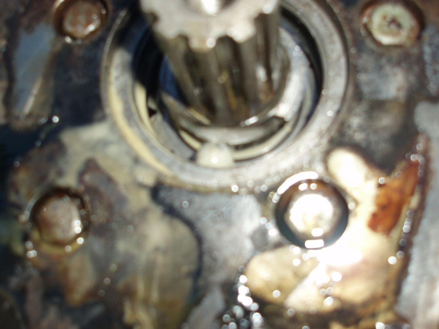
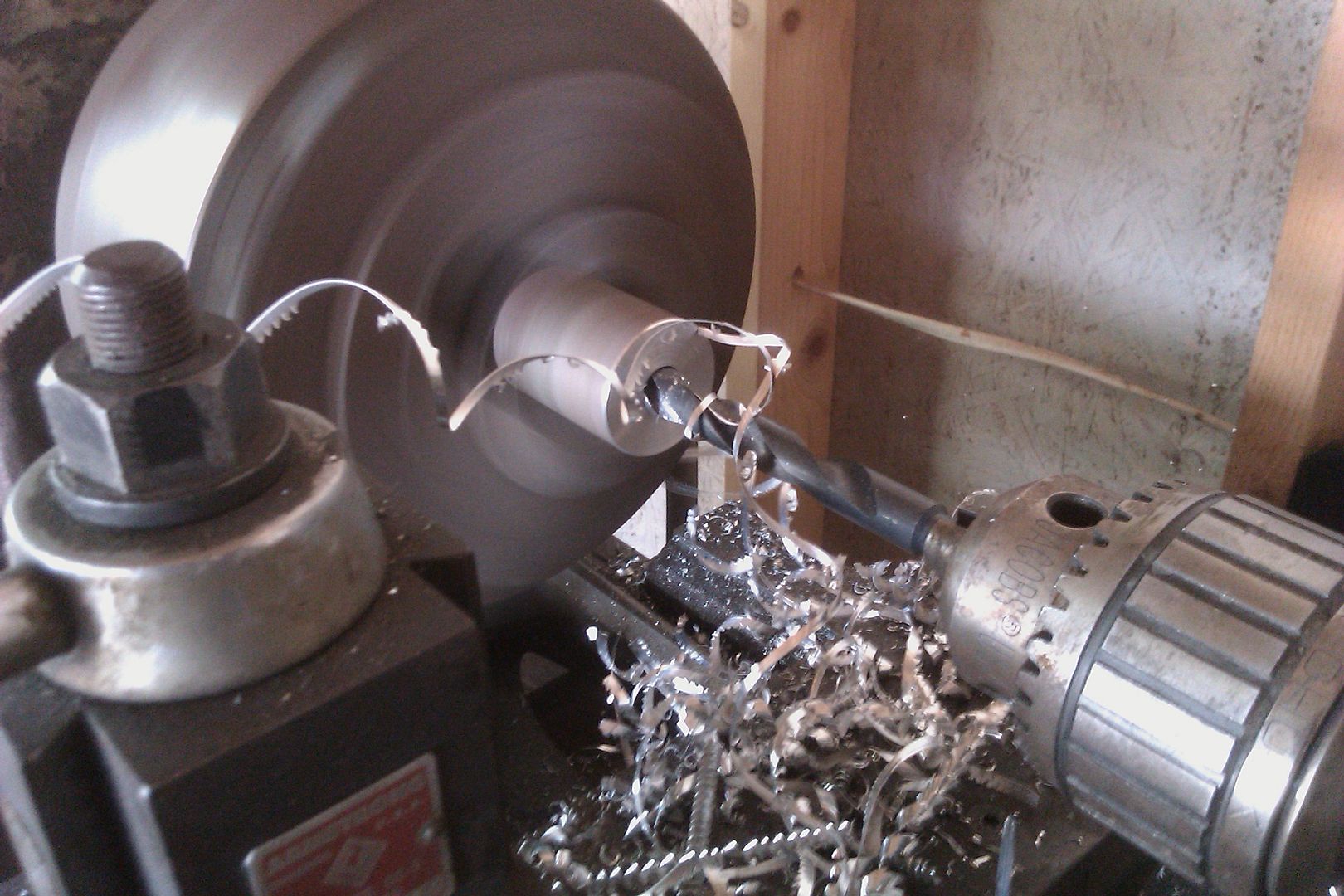
This is the custom input gear....

P1010219.jpg


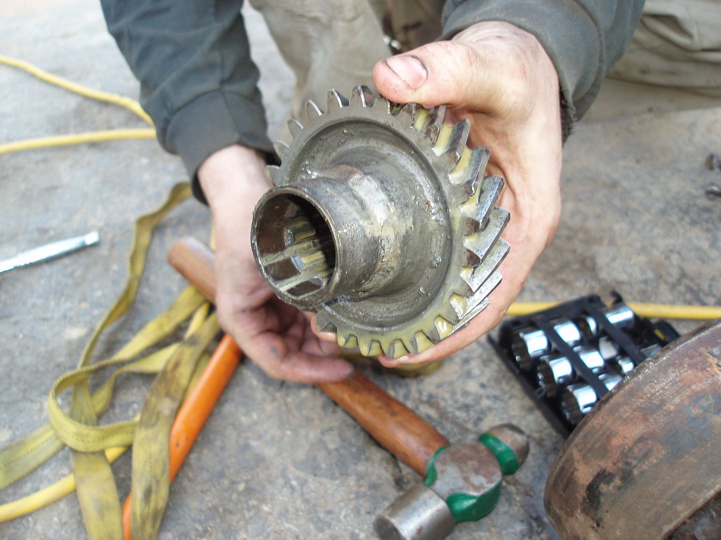
It is made from a factory D18 input gear that is bored out and pressed over a turned down sm420 2wd drive shaft yoke....

P1010221.jpg


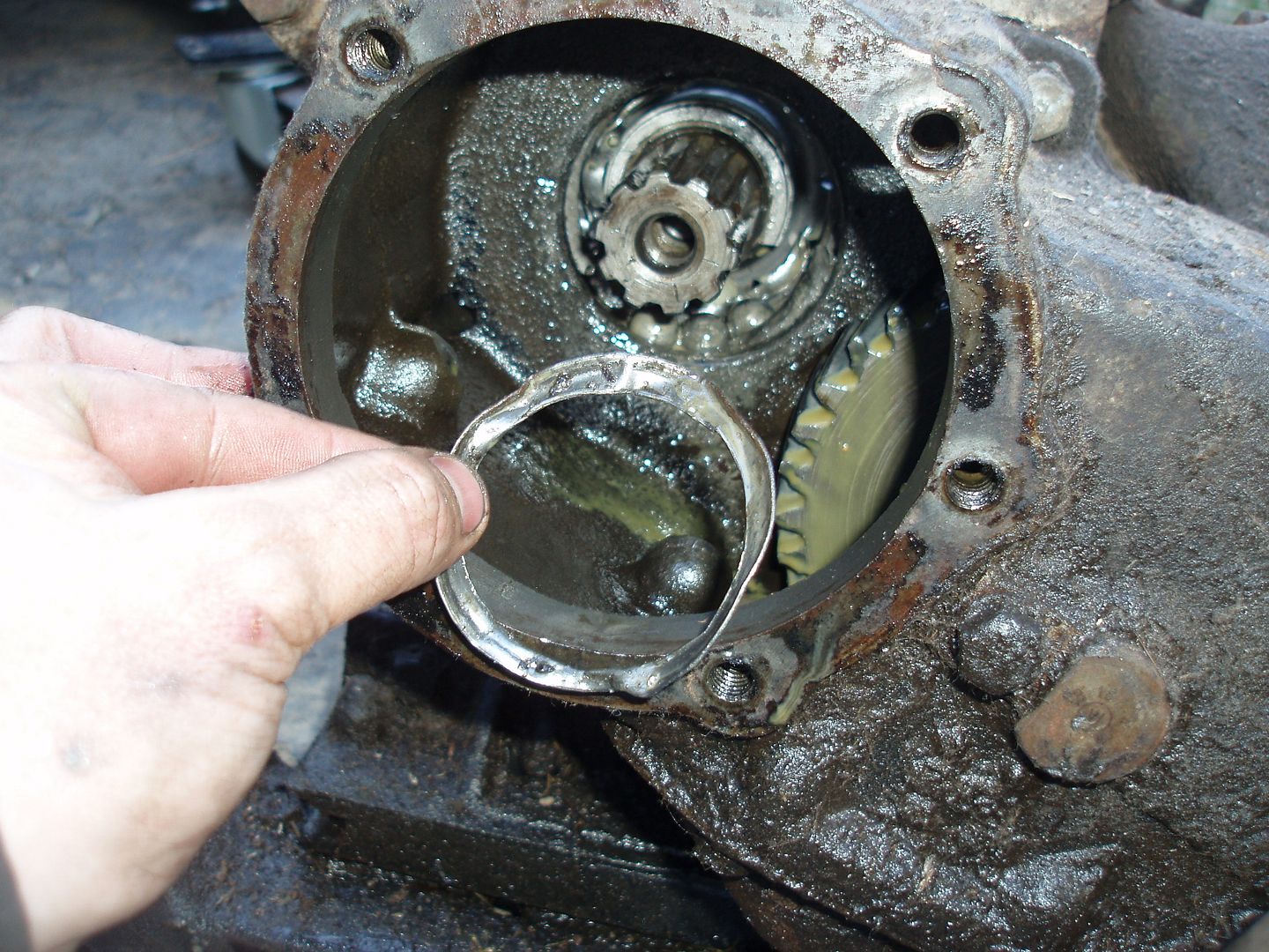
The rear output bearing one the sm420 was destroyed. It must have rusted this winter and popped when I pulled it out for the first time this spring. I'm pretty sure it had been going out of a long time.
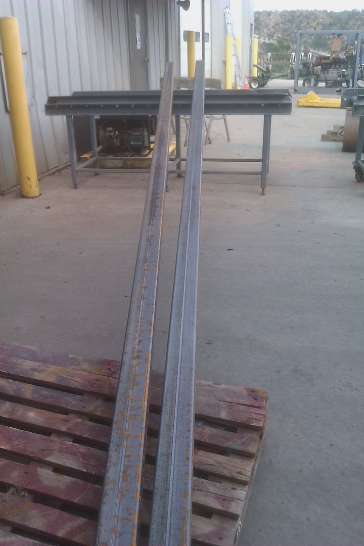
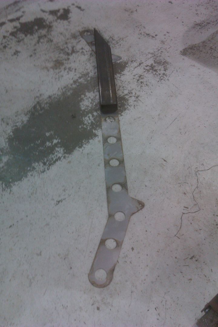
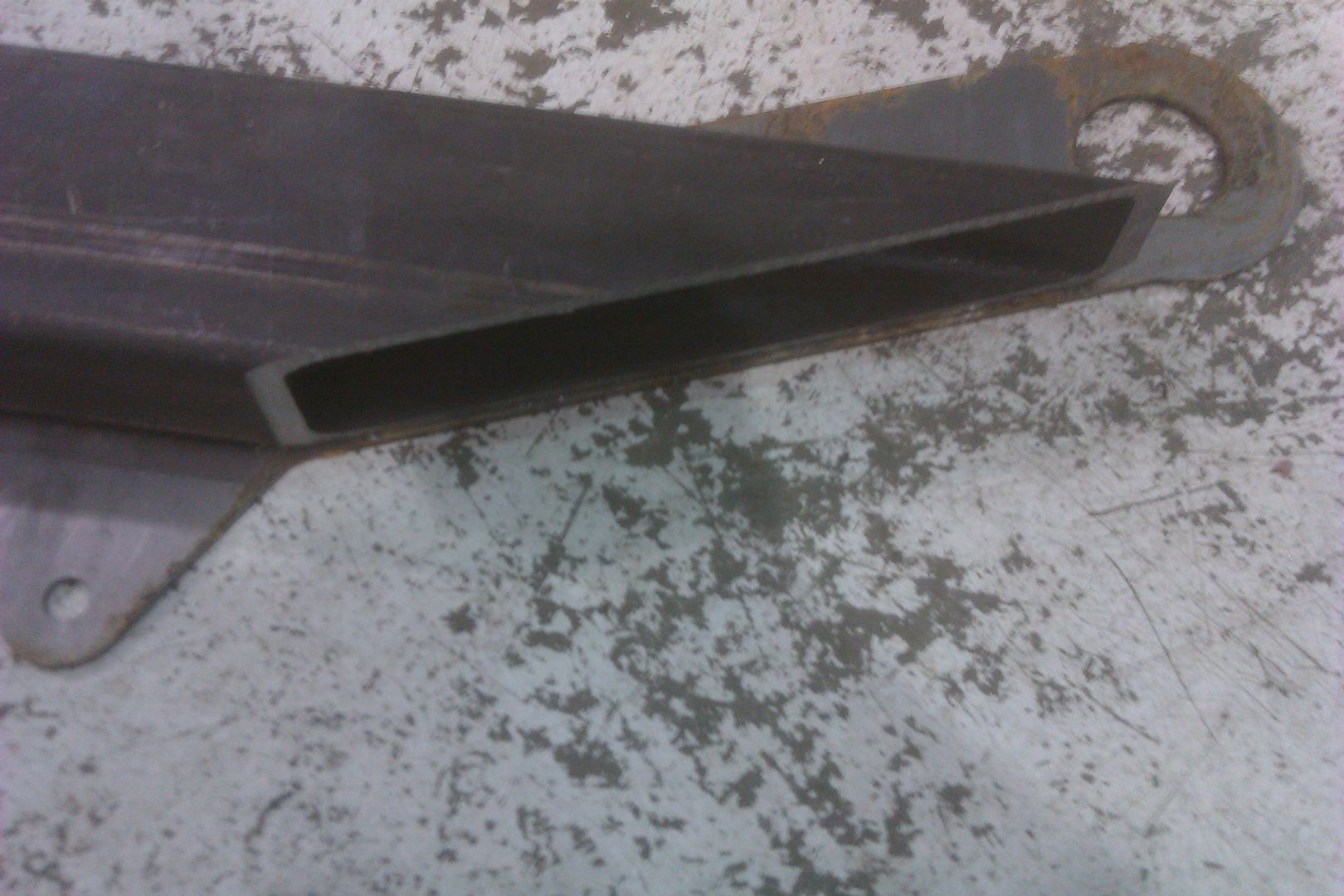
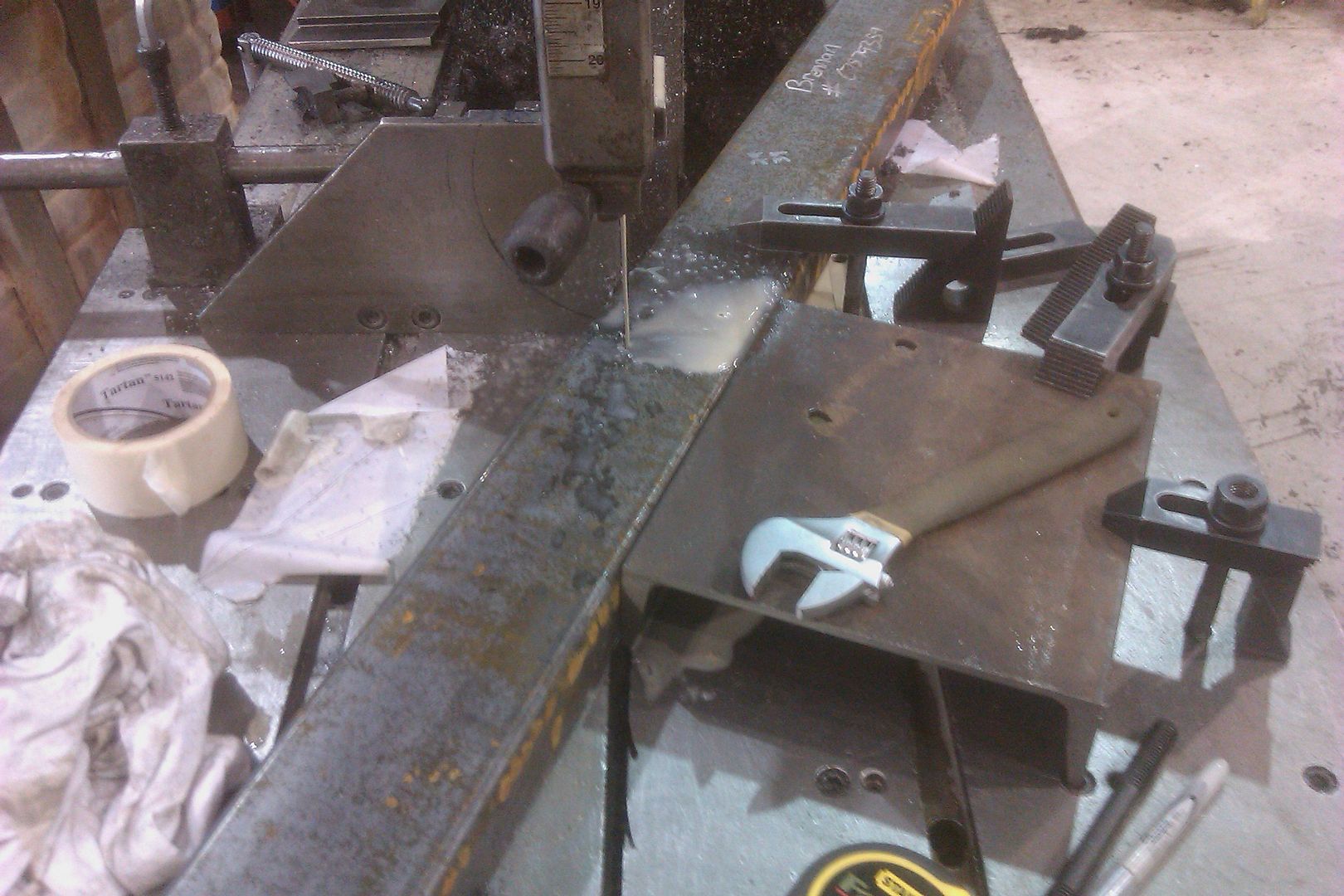
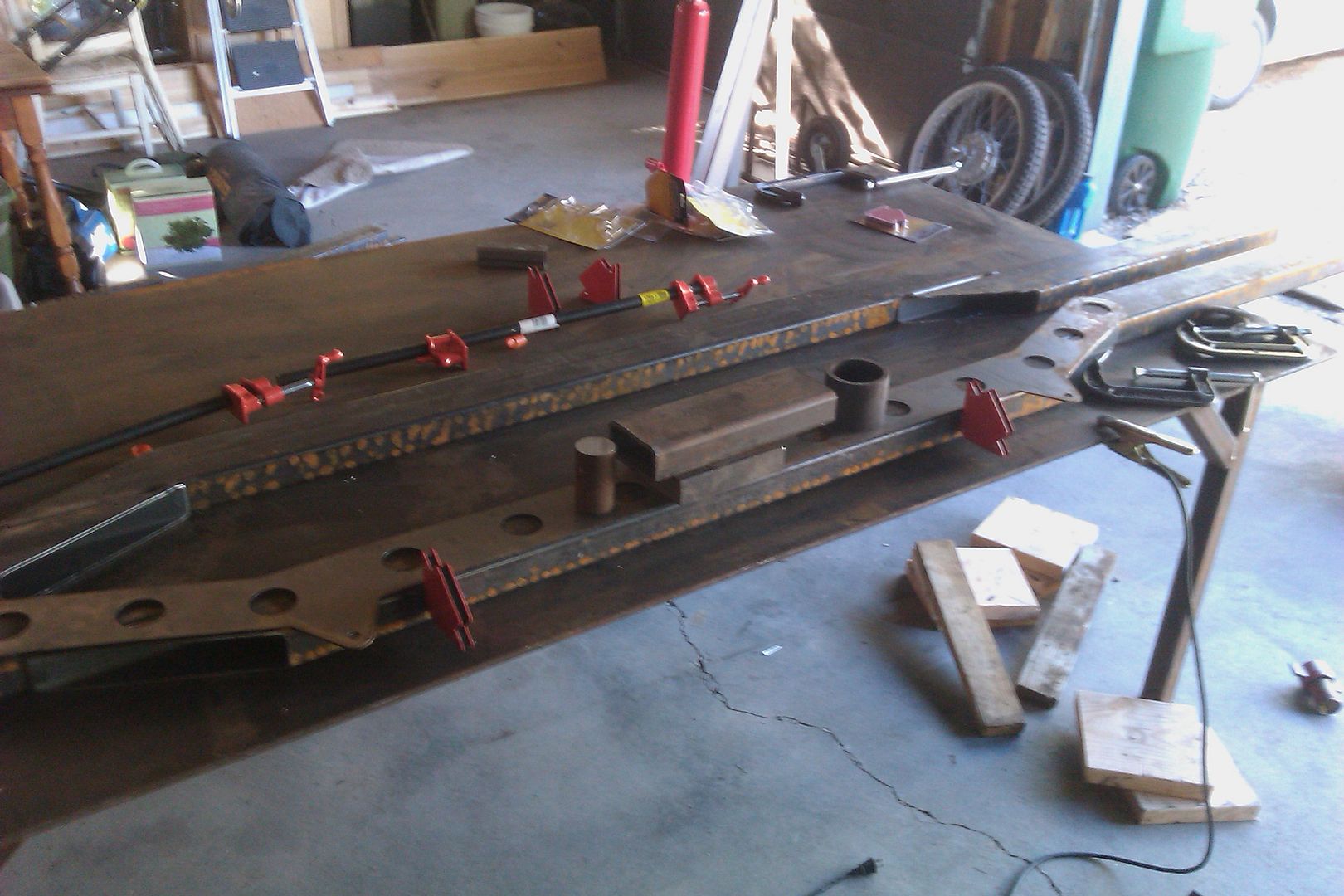
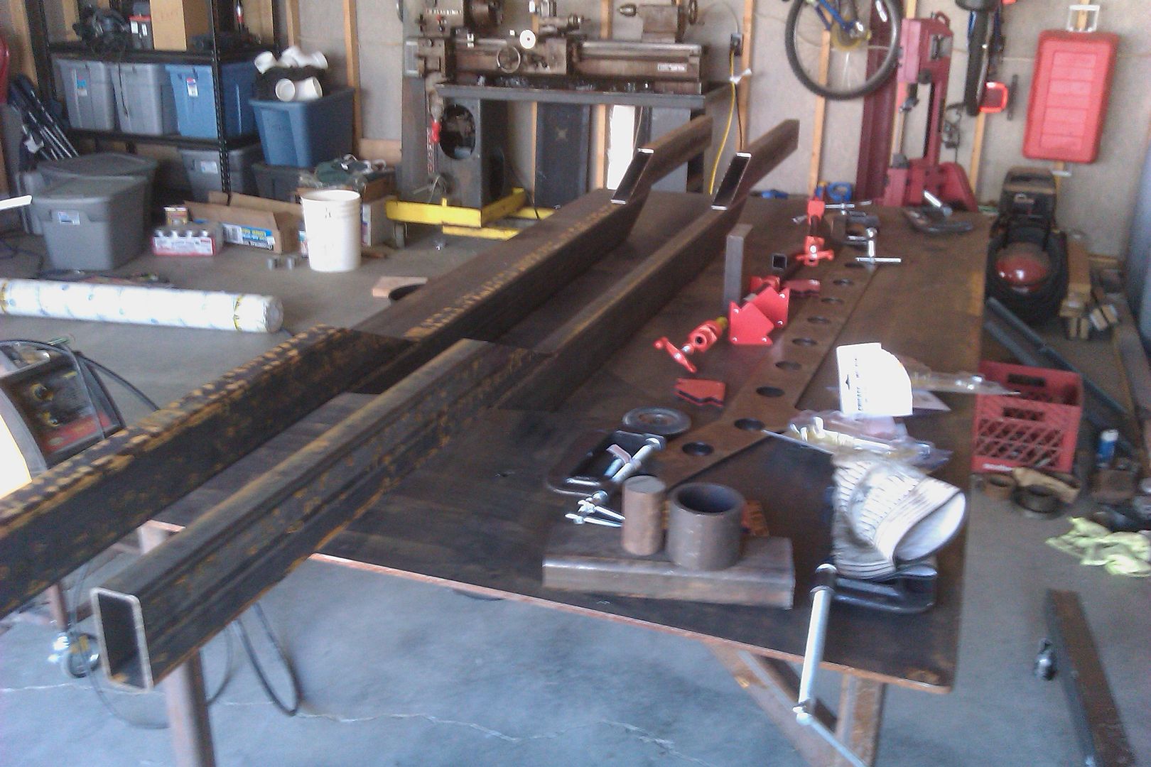
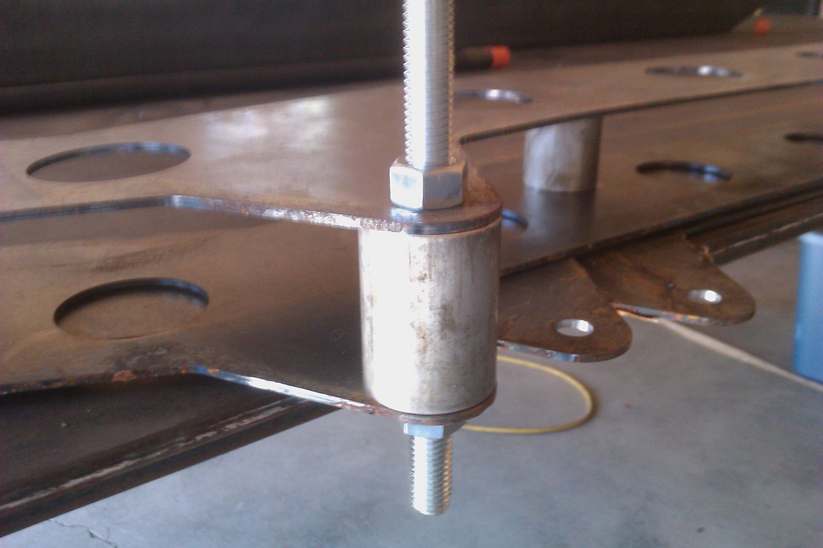
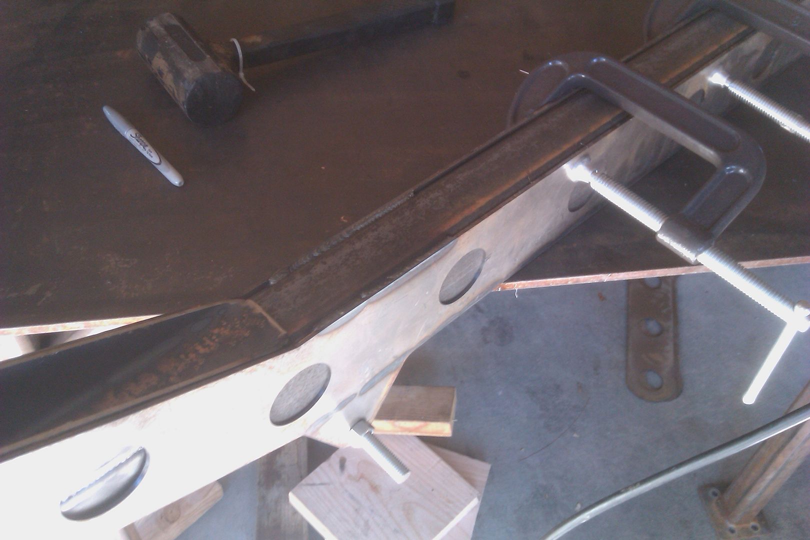
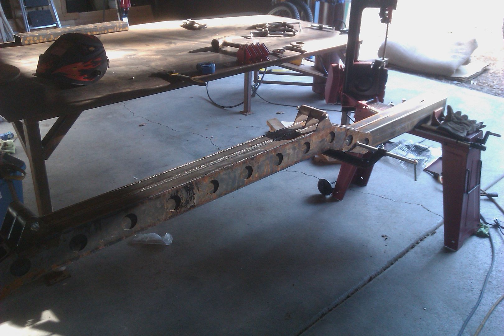
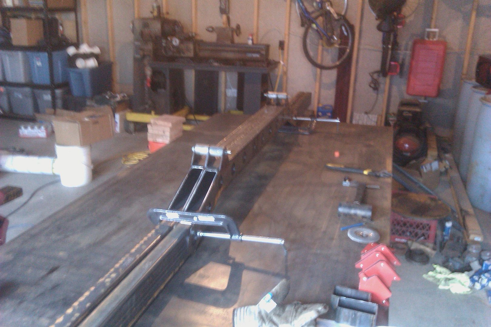
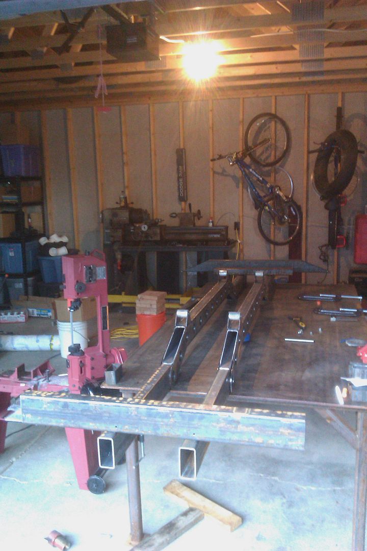
 

Metcalf

Expedition Leader
P1010222.jpg


This is the adapter once you get the t-case off. Its a bit of a pain to get the t-case off! There are some trapped blind bolts that are a little hard to get out. I'm pretty amazed it all fits! Its almost like its factory since its so dang short.

P1010225.jpg


That bearing is TOAST! You can also see some of the recessed bolts that hold the plate to the sm420.

I'll start putting it together tomorrow. I need to make some gaskets and take the t-case to the carwash!
 

Metcalf

Expedition Leader
From what I know it was homemade. VERY cool though. The packaging is just insane.

The story....

I bought it from guy 1
guy 1 got it from guy 2 that owed him money
guy 2 got it from the widow of the guy that built it.

If I had to guess, the powertrain was installed then the body installed over the top.

A quick update. It looks like I will have to swap the new SM420 guts into the old SM420 case. The fill plug on the side of the SM420 case has been shaved off and brazed shut to provide room for the front drive line yoke.

More later. I am off to EJS this afternoon.....
 

Metcalf

Expedition Leader
Winch faster woman! :sombrero:

IMAG0136.jpg


Rango is off to the new place! Its going to be SOOOOO nice to have a shop to work in!

As soon as we get settled I will start in on the project again. I would really like to get Rango rolling in the new configuration before EJS in 2012.
 

Metcalf

Expedition Leader
Time to start building again....

IMAG0146-1.jpg


Two 20' sticks of 2x4", 1/8" wall mild steel rectangular tubing. I think I see a replacement frame in there somewhere....

IMAG0147-1.jpg


First I had to set up a simple jig for the big band saw. I printed out a drawing for the angle using a CAD program. Then I used a scrap of c-channel to build a fence so I could repeat the same angle over and over again.

IMAG0148-1.jpg


It looks like this with a section of box tubing in it for a test cut....

IMAG0151.jpg


Here is one of the laser cut 1/8" thick side plates. These are designed to set the spring hanger position into the frame design. The Willys is getting stretched out to an 86" wheelbase overall with a +3" front and rear. I will have the ability to move the axles front and back with some offset centering pins to tune the wheel position in the rear wheel well and overall resulting overall wheelbase in front.

IMAG0149-1.jpg


I did a test cut on some scrap and this is the angle that was generated. This is more than close enough for an old willys frame. There will be a slight overlap for welding.

IMAG0152.jpg


Now it was time to cut all the sections for the rails, the rear bumper, and front bumper.....

IMAG0153.jpg


Sorry for the dark picture, but here are all the cut parts for the frame!

Next comes the assembly.....
 

Metcalf

Expedition Leader
I had to drag some stuff home last Saturday to help with the build....

IMAG0204.jpg


I picked up a used 4x8 welding table and a new engine hoist since I had to return my loaner after moving.

The table has a nice 3/8" thick top. I need to get out a long level and see how flat I can get it. I hope the table will allow me to build the frame nice and true. I will probably be cutting the legs down on the table and making it adjustable in height. I figure a lower height table will be nice later in the build....

I think I am going to have to do a little shuffling to build the frame, pull the tub off the old chassis, remove the engine, and start putting stuff back together.

I hope being able to build the jeep on a nice flat table should make things turn out a little better in the end.....

Hopefully the frame is going to get assembled this weekend.....I already have the parts on the table. I am just trying to work out a way to clamp and hold everything down.
 

Metcalf

Expedition Leader
Today I started putting together the new frame....

IMAG0223.jpg


First thing I did after I checked that the table was level 'enough' was to lay out all the main rail parts. Since they are symmetrical I was able to lay them out 'top to top' and everything wanted to nest together pretty good without too many clamps. I ended up having to use some added weight to the top of the rails to get everything to lay flat. I also checked the position of the rails with the side plates. This is important for later, but basically the rails don't have to be exactly tapered and in position. You only have to have enough room for the side plates to fit on the frame...

IMAG0225.jpg


I cleaned up the main joints with a wire brush where the tubing the forms the rails stacks on top of each other.

IMAG0224.jpg


I tacked each rail together with some 1/2" long stitches on towards the ends.

IMAG0227.jpg


After the rails where tacked I flipped them over and clamped them together like this. This allowed me to suck the rails back together and flat on each other once the opposite side was tacked. The tack weld will pull the rail apart slightly....

IMAG0228.jpg


After welding the tubing on both sides together you have a frame rail....

IMAG0230.jpg


Next I had to make up some 2" dia, 2.020" long bushings. These will help align the side plates and the frame rails to each other later on. They have a .510 hole in through the middle. Even a small lathe comes in handy at home.

IMAG0231.jpg


Thinking ahead a little bit, I drilled some pilot holes in the front bumper on the little drill press. This should make some things easier down the road.

IMAG0233.jpg


These are how the aluminum spacers work. They basically help keep the distance between the side plates square and exact. I used a cheap section of 6", 1/2-13 all thread and some nuts to hold the plates together.

IMAG0235.jpg


I then laid the top of the belly section of tubing over the edge of the table. The side plates are then positioned over the frame rail. At this point the position of the side plates isn't super critical front to back as long as they have enough room. I used a dead blow to snug the side plates against the table to keep them flush with the top of the belly section of the rail. At that point I started welding the side plate to the frame tubes. I used 4" stitches of weld alternating side to side removing the clamps as I went....

IMAG0235.jpg
 

Metcalf

Expedition Leader
Then I flipped the rails over and welded the other side. I used the clamps to pull the joint as tight as possible.

IMAG0236.jpg


Then I welded the 2nd rail on the top and bottom.....

IMAG0237.jpg


Once the frame rails where welded I bolted them together with the spring hanger mounts. I was able to use the aluminum spacers at this point again. I think this keeps everything very straight and true between the left and right frame rail. At this point the rails are measured for final length and trimmed while bolted together. This makes both rails the same length and square at the ends. I think this is easier than trying to make the rails the same length during the clamping and welding process.

IMAG0238.jpg


You can see the difference in rail length before cutting....

IMAG0239.jpg


After cutting, both are the same length and square to each other...

IMAG0240.jpg


After reapeating this process on the other end both rails are now the same length. The rails where then moved to the table. At this point the frame is about as heavy as I could lift comfortably.

IMAG0242.jpg


Next I cut up the material for a rear bumper spacer, added the front bumper, and the rear bumper to the table. Next I will be laying out the frame rails square and welding in the front bumper and rear crossmember right behind where the rear bumper is to be welded on. I am going to wait to weld the rear bumper in place until I get the body tub on the frame. I am not a 100% sure where it is going to end up vertically......

First I need to weld up all the speed holes, cap the angle cuts, etc.....

More soon.....
 

reece146

Automotive Artist
Looking good. I like the idea of building the pieces and then cutting to correct length after the fact. It pretty much guarantees the major datums are correct between the end points and the leaf hangers being sync'ed.

What do you have in mind for corrosion protection? Spray on stuff or were you going to get it dipped?

I welded a bunch of stiffening plates on the unibody of my personal XJ and am somewhat concerned about corrision between the layers. I got some of Eastwood's chassis protection stuff but I still don't have a "warm fuzzy" about it. The next XJ I build I'll be dipping the unibody I think.

In your climate it's probably less of an issue. I'm in the north east.


Metcalf

Expedition Leader
Thanks, I figured that cutting the frame after would get it just a bit closer. Now I just need to get it square when I weld in the bumpers/cross-members. I am thinking that I might cut two lengths of bar stock to the proper length to span the distance between the spring hangers from left to right. Then face the ends in the lathe to make it all square. Then drill and tap the ends for some 1/2-13 threads. I think this would really help keep the frame square, especially with the aluminum spacers installed.

I am pretty lucky to live in the southwest. I don't think things really rust that much here :) That tubing has been outside for months in the stock rack at work. I am going to try and seal up all the ends of the frames and weld up the side plates completely. I will then probably just spray the frame in primer and some olive drab. Nothing fancy really.
 

Forum statistics

Threads
188,444
Messages
2,905,028
Members
230,360
Latest member
TNielson-18
Top