Metcalf
Expedition Leader
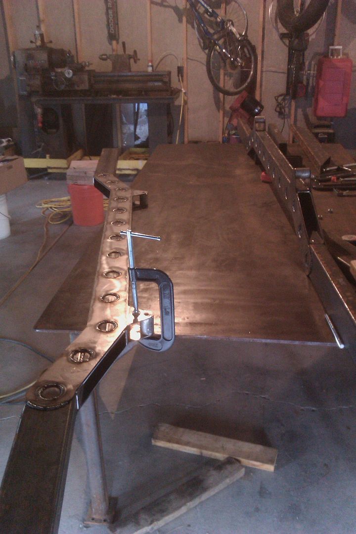
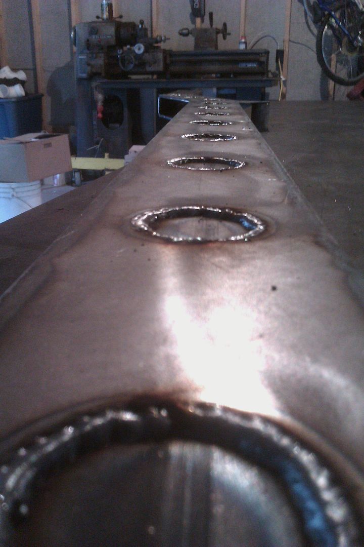
Welding up circular holes sucks....
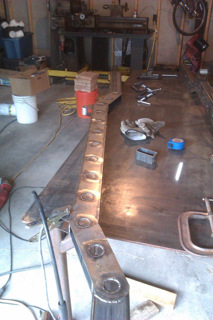
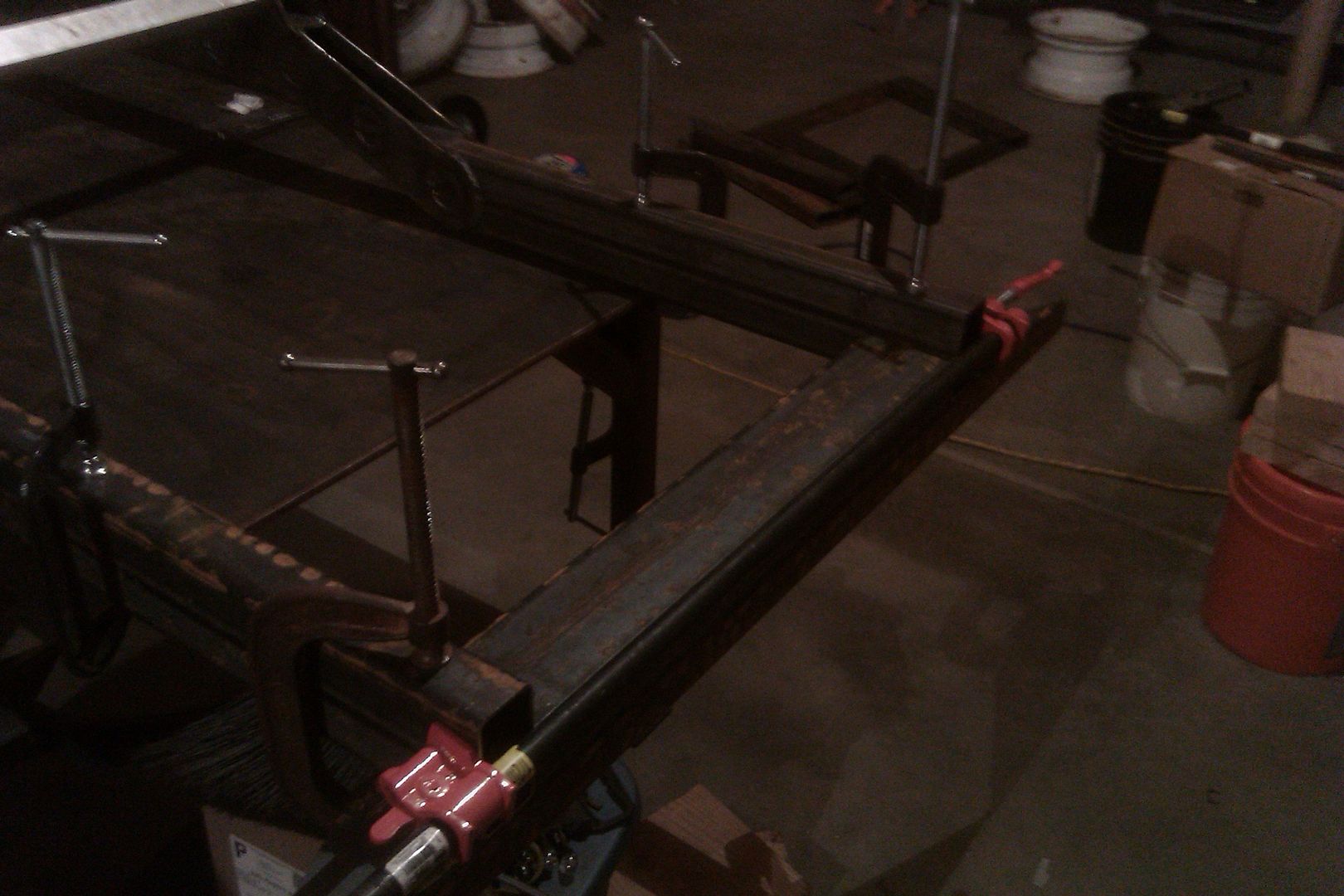
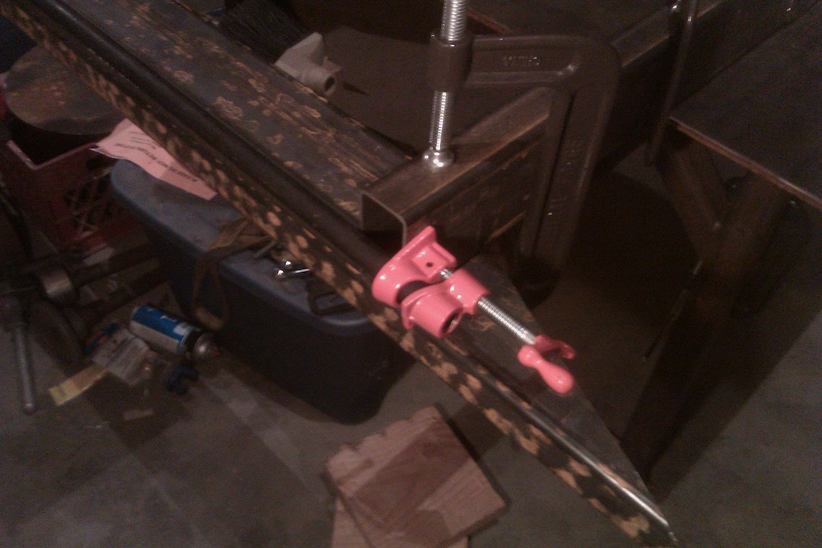
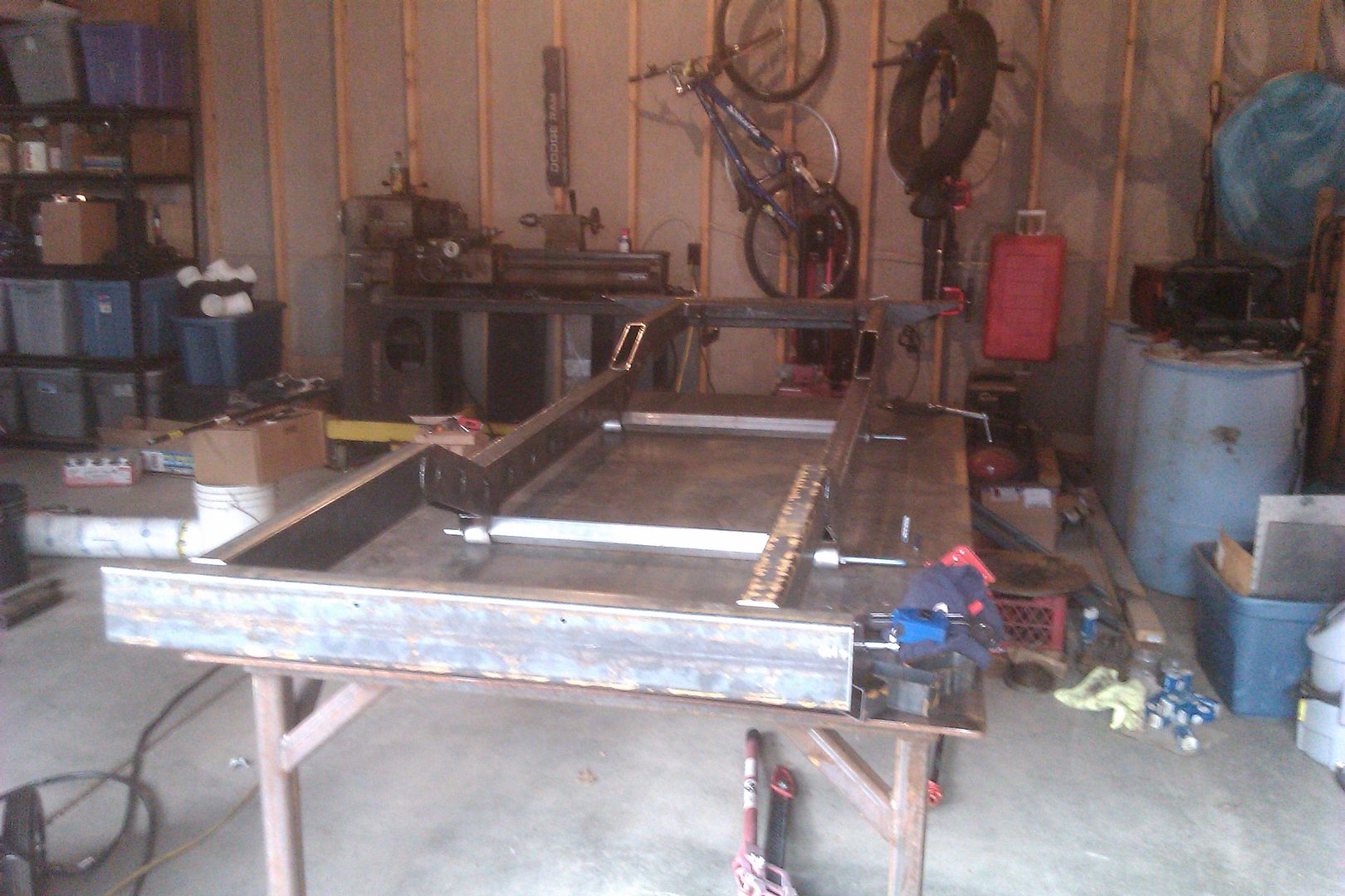
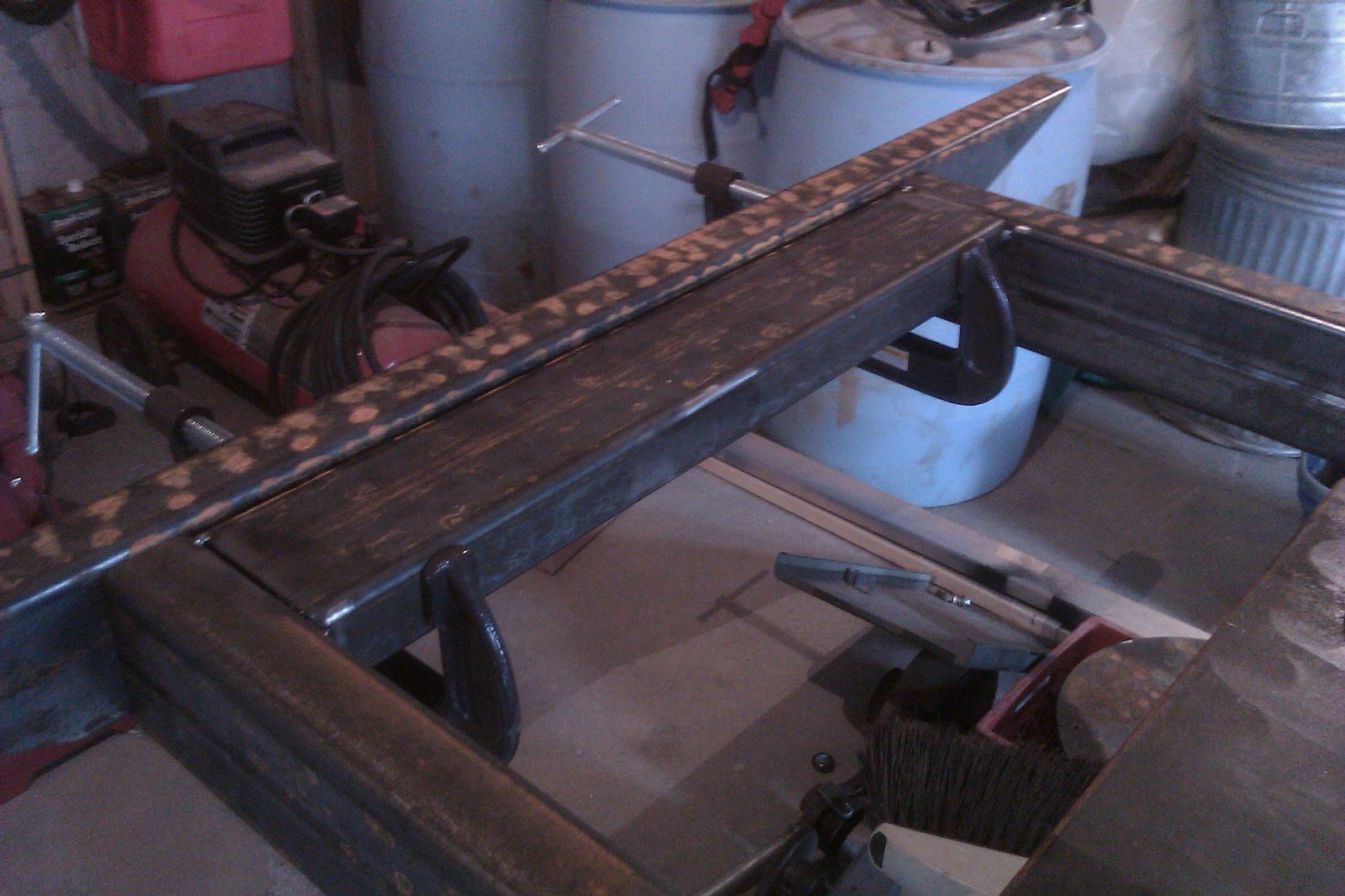
I got all the speed holes in one frame rail welded. That was much harder than I would have thought. Welding around in a circle is not easy at all! Overall they are decent and will hold together, but they are not what I would call pretty!
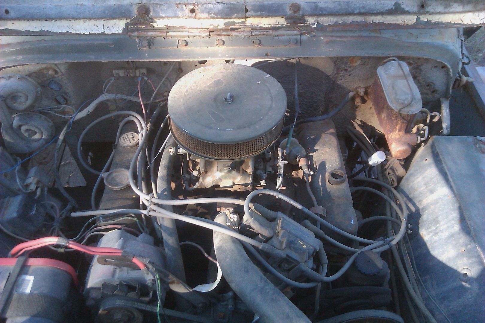
I took a picture or two of the engine compartment making some mental notes on stuff. Boy, there really isn't a lot of room. The engine was also installed a little offset at an angle by the previous owner. It always worked fine. I am going to shoot for 1.25" to the drivers side and go from there.
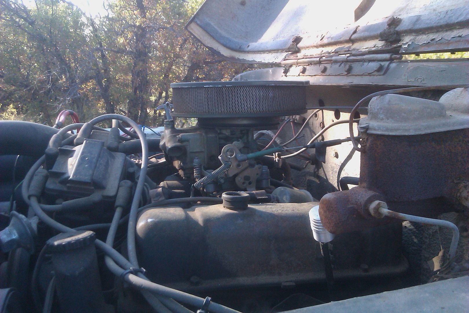
There is a little more room with the air cleaner than I thought, but not a ton. the air cleaner has a slight raise in the base that could go away with a little work. The air cleaner is about as small as I would want to run. The carb has a 1/2" thick adapter under it also that might be able to be redone?
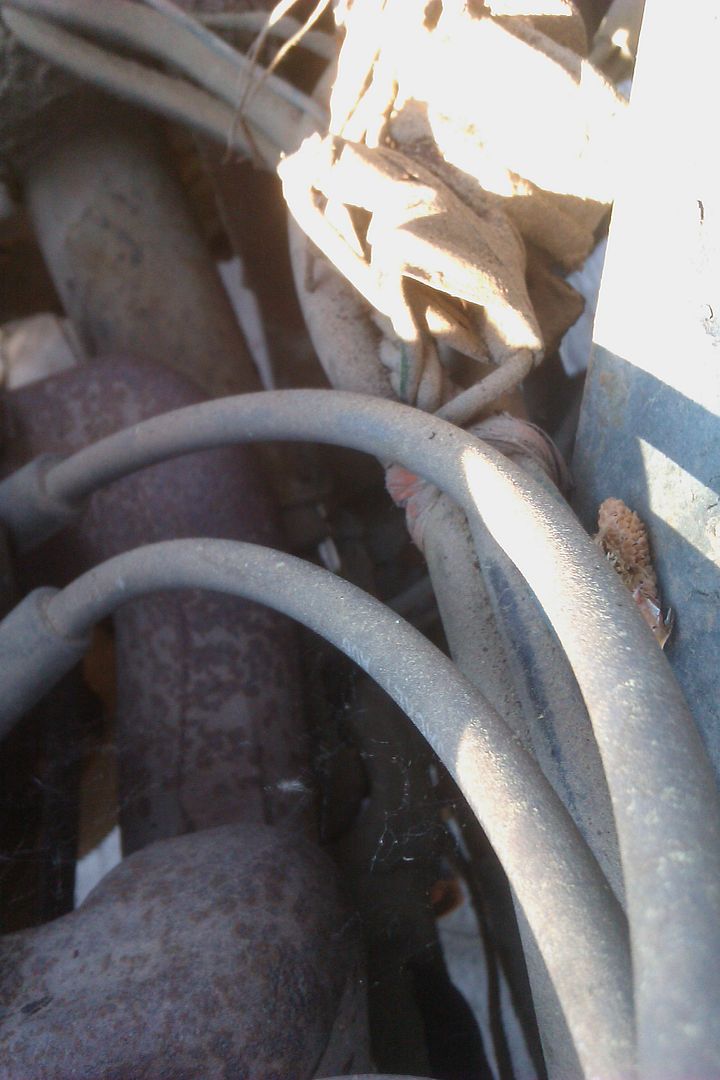
That is a really bad view of the steering shaft joint at the column. It is VERY close to the drivers side exhaust manifold! With the new lower seating position the steering column angle needs to change (down at the steering wheel. I think lifting the motor will give enough room to work around. The column connection at the dash needs to be redone also. The steering box pull is also pretty dang close to the drivers side inner fender.
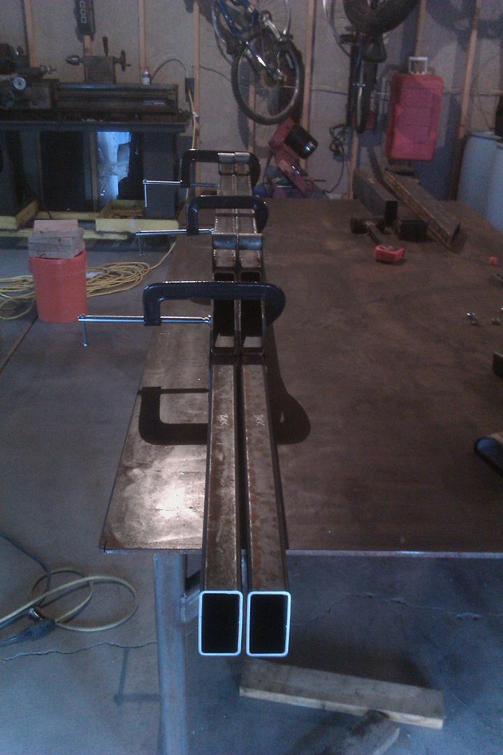
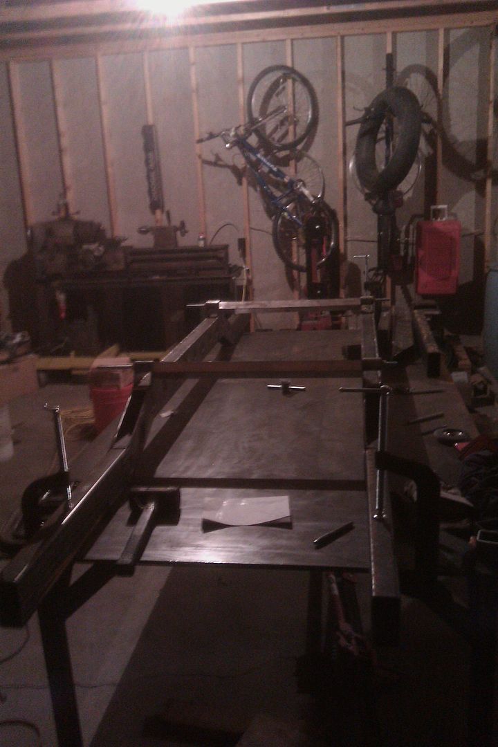
I will do a little more tomorrow. My search for some 1.75x1/8 flat bar is still ongoing....
I got all the speed holes in one frame rail welded. That was much harder than I would have thought. Welding around in a circle is not easy at all! Overall they are decent and will hold together, but they are not what I would call pretty!
I took a picture or two of the engine compartment making some mental notes on stuff. Boy, there really isn't a lot of room. The engine was also installed a little offset at an angle by the previous owner. It always worked fine. I am going to shoot for 1.25" to the drivers side and go from there.
There is a little more room with the air cleaner than I thought, but not a ton. the air cleaner has a slight raise in the base that could go away with a little work. The air cleaner is about as small as I would want to run. The carb has a 1/2" thick adapter under it also that might be able to be redone?
That is a really bad view of the steering shaft joint at the column. It is VERY close to the drivers side exhaust manifold! With the new lower seating position the steering column angle needs to change (down at the steering wheel. I think lifting the motor will give enough room to work around. The column connection at the dash needs to be redone also. The steering box pull is also pretty dang close to the drivers side inner fender.
I will do a little more tomorrow. My search for some 1.75x1/8 flat bar is still ongoing....
")
")