Get your tickets to THE BIG THING 2026!
You are using an out of date browser. It may not display this or other websites correctly.
You should upgrade or use an alternative browser.
You should upgrade or use an alternative browser.
How to make a cheap isolated dual-battery setup for $50
- Thread starter evldave
- Start date
dwh
Tail-End Charlie
Rule #1:
When sizing wire for supplying a load FROM a battery; Size the wire (and fuse) to the appropriate size for the MAXIMUM expected amp load (and DON'T forget that as the battery drains, the voltage goes down and so the amps go UP). Then, OVERsize the wire as needed to compensate or reduce voltage drop to an acceptable level AT THE MAX AMP LOAD (lowest voltage).
Rule #2:
When sizing wire for CHARGING a battery; Size the wire (and fuse) to the appropriate size for the MAXIMUM expected amp load. Ignore the voltage drop. OVERsizing is not needed.
Exception to Rule #2:
If you are designing a system where every watt counts - such as a bleeding edge off-grid solar electric system - you MIGHT want to OVERsize the battery CHARGING wire in order to achieve maximum efficiency of the system (you certainly WILL want to OVERsize the inverter supply wire). For a fixed location permanent solar electric installation, you can take into account efficiency of the battery (or bank), the efficiency of the charge controller, the efficiency of the inverter, the efficiency of the PV modules, the expected daily consumption, the expected daily insolation (which is based upon the photon angle of incidence (a combination of latitude and PV module installation angle) and average weather), hours of "good sun" per day, hours of "partial sun" per day, etc., etc., etc., ad nauseum...(But don't even bother doing the math for a max efficiency system for a mobile rig with fixed flat-mount PV modules that might be 7,000 miles from the equator at sea level one day, and two weeks later is 500 miles from the equator and at 9,000 feet, and during the two weeks the truck was never once parked exactly level and during the whole trip, during peak sun hours the damned thing was moving around uphill and down, through tunnels, under trees, etc.)
--------------------------------------------------------
Now the real world case histories...
wrc says he's got a 130a alternator. Says he'll see peaks of 110a. Says when he cuts in his added #2 AWG charging wire, he gets better performance.
According to the NEC wire ampacity table, #2 with insulation rated for 60c temp is rated to carry 95a. With 75c insulation, 110a. With 90c insulation, 130a.
When wrc cuts in his #2 wire, is he running OVERsize wire?
NO!
He is complying EXACTLY with my rule #2.
When he cuts out his added charging circuit of #2 wire then he's running the factory installed UNDERsize wire.
And seeing decreased charging performance.
Well, no ******** Sherlock. I coulda told you that would happen.
Practically every factory installed vehicle charging system IS running UNDERsize wire.
By going to a #2 wire size, wrc FIXED what WAS broken.
WHY is wrc arguing with me? I dunno. Prolly doesn't wanna pay me that beer he owes me.
Diplo says he's got a 200a alternator. Got a hunky-dory computerized voltage regulator. (And I gotta tell you, I WANT that. Might have to figure out if it's possible to steal one from somewhere.)
Diplo sees regular charge rates of 150a. I don't really know what size wire he's running. I must not have been paying attention when he said it. Something about #1 (or was it 1/0?). Maybe even running doubled up wire. Dunno. Still, let's look at the wire ratings and see what we see....
#1 with 60c insulation - 110a, #1 with 75c insulation - 130a, #1 with 90c insulation - 150a. 1/0 would be 125a, 150a, 170a.
Is Diplo running OVERisze wire?
NO!
If he's running either #1 or 1/0 - he's running UNDERsize wire.
For a 200a max (the alternator's current limit) my rule #2 would dictate 3/0 with 75c insulation (though you could cheat and run 2/0 with 90c insulation and get close enough)
WHY is Diplo arguing with me? I dunno. Prolly a conspiracy. I suspect he's in cahoots with wrc to cheat me out of my rightful beer allocation.
Honestly, I wish you two jokers would stop jibber-jabbering at me about running oversize wire to compensate for voltage drop when NEITHER ONE OF YOU IS RUNNING OVERSIZE WIRE!
[And what the hell, while I'm on my soap box I got a bone to pick with someone else. (Not naming names here.)
Now don't take this personally, but I'm going to do you the courtesy of speaking to you as I would have spoken to one of my apprentices back when I was in the trade...
Dude...******? I've seen you make several boneheaded statements. So far, I've just let 'em slide. In particular, allow me to point out when you said that MPPT stands for MultiPoint Power Tracking. No. It. Does. Not. It stands for Maximum Power Point Tracking. I really wish you'd break open the books and at least start to get a grip on the basic nomenclature before you start trying to teach a journeyman about electricity!]
Last edited:
dwh
Tail-End Charlie
And while I'm doing cave paintings, might as well do one more. We'll call this one: How to fool yourself.

Okay, so Loop 1 is at 11v.
You stick multi-meter B on the battery terminals, thereby creating Loop 2, which consists of the meter and the battery. In other words; a SHORT circuit.
What voltage does meter B see?
It sees the battery voltage.
You stick multi-meter A on the terminals of the power supply, thereby creating Loop 3, which consists of the meter and the power supply. In other words; a SHORT circuit.
What voltage does meter A see?
It see the voltage POTENTIAL of the power supply.
NEITHER METER is reading the voltage of the charging loop, though you can guess the voltage of the charging loop once you know the voltage of the battery, because the battery regulates the voltage of the charging loop. That is, until the charging loop voltage reaches parity with the supply's regulated voltage, then the power supply regulates the voltage on the charging loop, but you can still guess the charging loop voltage by reading the battery.
Now exactly how in hell do you expect to measure voltage drop with a goofy test setup like that?
Last edited:
dwh
Tail-End Charlie
Didn't I title my last post, "violent agreement"?
How would I know? I never even notice post titles. They're like dreams to me - I forget 'em 2 seconds after I see 'em.

I'll buy you the beer, but you gotta buy me a decent Merlot.")
Screw it. Let's just go in halves on some cabernet sauvignon.
dwh
Tail-End Charlie
Deal, but please do give my last post a sanity check. I know what I meant to write, but we non-EE types don't always get the details right.
K, but mañana. Gotta run now.
dwh
Tail-End Charlie
So what's the verdict? Can you fully charge a 120AH house battery from the alternator or not?
Absolutely yes. But be prepared for it to take a few days drive time to get it done.
jdlobb
Adventurer
Absolutely yes. But be prepared for it to take a few days drive time to get it done.
how's the math on that work? If the alternator outputs 120 Amps, how much is the engine drawing just to run? Where is it all going? Math me bro.
dwh
Tail-End Charlie
how's the math on that work? If the alternator outputs 120 Amps, how much is the engine drawing just to run? Where is it all going? Math me bro.
Only have a few minutes.
Electricity doesn't exist until you use it. It's only a potential. Hoover Dam has a 2000 megawatt potential. So the water is flowing full speed and the turbines are spinning and you hook up a 40w bulb to it.
How much electricity does it make?
40 watts.
Same with any power supply - battery charger, alternator, whatever. Your alternator can *potentially* produce 120a, but it won't unless there is 120a of load sucking the power out of the alternator. If everything in your truck is only pulling 6a, then your "120a" alternator is producing 6a.
The extra 114a doesn't "go somewhere". It doesn't exist. It's only a potential.
jdlobb
Adventurer
Only have a few minutes.
Electricity doesn't exist until you use it. It's only a potential. Hoover Dam has a 2000 megawatt potential. So the water is flowing full speed and the turbines are spinning and you hook up a 40w bulb to it.
How much electricity does it make?
40 watts.
Same with any power supply - battery charger, alternator, whatever. Your alternator can *potentially* produce 120a, but it won't unless there is 120a of load sucking the power out of the alternator. If everything in your truck is only pulling 6a, then your "120a" alternator is producing 6a.
The extra 114a doesn't "go somewhere". It doesn't exist. It's only a potential.
Then I guess I don't understand why the house battery can't suck that power out of the alternator. What is the limiting component? Wires, charge controller, battery?
dwh
Tail-End Charlie
Then I guess I don't understand why the house battery can't suck that power out of the alternator. What is the limiting component? Wires, charge controller, battery?
Battery and wire.
There's no charge controller per se. There's a voltage regulator. You don't really need a charge controller on a normal vehicle, because the only thing the battery ever does is start the vehicle, which only draws down the battery like 0.1 or 0.2 amp*hours each time you start the vehicle, and the battery only needs a tiny little "top up" every time you start the vehicle. That only takes a few minutes.
Diplo's dual alternators and computerized multi-stage voltage regulator is way overkill and totally not needed for a normal vehicle, which makes me wonder if maybe it's part of a "camper special" or "heavy duty" option package. No manufacturer is going to spend the money to rig a truck like that without a reason.
The voltage regulator (on a normal vehicle) holds what I call "the 12v bus" (a.k.a., the electrical system) at a certain voltage, or more precisely, a certain voltage range. Anything connected to the bus that sucks power out of the bus draws down the bus voltage. The voltage regulator will switch the alternator's "clutch" (field coil) on and off to supply however much power is needed to hold the bus voltage in the specified range.
A load, like say an inverter, radio or headlights is just going to draw however many amps it needs from the bus to do what it needs to do.
A battery is different. It can be either a power supply or a load, so power only flows IN to it when the voltage of the battery is lower than the bus voltage (the battery is a load). If the bus voltage is lower than the battery's then power flows from the battery to the bus (the battery is a power supply).
How much power flows into the battery depends on A) how much lower the battery's voltage is than the bus voltage (the lower it is, the steeper the gradient, the more power will flow through it), B) the resistance of the battery, which slows down (or even stops) power flowing *through* it, and C) any added resistance, such as the wire.
The battery's resistance plots on a curve. The curve is low in the middle and high at both ends. So a dead battery has a high resistance, and a nearly full battery has a high resistance. A totally full battery has a very high resistance and has a voltage equal to the bus voltage, so there is no gradient and no power flows "downhill" from the bus to the battery.
The primary limiting factor is generally the battery's resistance, and the wire is a secondary limiting factor. During times when the battery's resistance is very low and it can accept (draw) a lot of amps from the bus, then the wire can become the primary limiting factor. When the wire acts as a limiting factor, how much it limits is determined by how many amps are flowing - the more amps flow, the higher the wire's resistance. This is normally expressed as "voltage drop", though that expression is not really appropriate unless you are talking about the battery acting as a power supply.
Then, there is this thing called "surface charge". When power flows through a lead-acid battery (flows in or out), electrons build up (temporarily) at the interface between the lead and the acid. When charging, this creates a situation where the battery voltage "looks like" the battery is charged, so the battery's voltage is the same as the bus voltage. Well, there goes your voltage gradient. Not much power will flow. The built up electrons will dissipate into the electrolyte, so the battery voltage will fall, but as soon as it does, more power flows and builds up the surface charge again. So once the battery reaches a surface charge equal to the bus voltage, the power that flows through falls off a lot and charging slows way down.
On a normal vehicle, when you add a big secondary battery and then drain it low, it can take anywhere from 12 to 36 hours of drive time to fully 100% recharge the battery.
dwh
Tail-End Charlie
follow up question, while it may take 12-36 hours of drive time to get to 100%, how variable is the charge rate? Will it, for example, get to 80% in 1 hour, and then take 11 hours for the last 20%? What is the equation that governs the charge rate in the battery?
There's no single equation. (no GUT...yet
), because there are several variables involved. What is the voltage, or voltage range of the voltage regulator?
How far down is the battery? (Expressed either as SoC (State Of Charge) or DoD (Depth Of Discharge).)
What size are the wires?
What does that particular battery's resistance curve look like? (Each brand and model has its own curve.)
What's the temperature of the battery? (Resistance goes down when temperature goes up.)
What's the age of the battery? (Resistance goes up over time.)
How many times has it been cycled, and how deeply? (In other words, how much sulfation/plate corrosion/etc. does it have?)
Also, batteries (and wires) aren't 100% perfectly efficient (nothing is). So you'll have to supply usually around 120% of whatever watts the battery is down by. Say it's down by 50ah, you'll have to supply it with around 60ah before it'll be fully charged.
If you want math, there's plenty. It's been done to death really. Try these for a start:
http://www.battcon.com/papersfinal2002/davispaper2002.pdf
https://www.google.com/search?q=lea...-IGAAw&sqi=2&ved=0CAcQ_AUoAg&biw=1366&bih=653
So it just depends on the particular situation. You might get from 50% to 80% in 2 hours and then spend 8 trickling to get it up that last 20%, or you might get from 20% to 85% in 15 hours and spend another 15 getting it pushed up that last 15%.
In general though, it's not a "stepped" process, like a multi-stage charger with a "constant current" bulk stage. Voltage regulated alternators are a "constant voltage" type charger, so it's pretty much a smooth curve where the voltage of the battery rises, and the current flowing through the battery falls.
(And don't take that as gospel in the case of Diplo's system. I haven't had a chance to think deeply about what is really happening with his rig - I've only just yesterday got a grip on the *structure* of his setup - but I suspect that the "duty cycle" sensing combined with the ability to go to a really high voltage potential (15.5v) is either acting as a true constant current charger, or is at the very least doing a bloody good simulation of one. (Though if it was true constant current, I would think with a 250a potential, it would be set to a higher constant current rate than 150a.))
A 2-stage charger (such as Iota without IQ/4 brain module) which can do both constant current (current regulated) and constant voltage (voltage regulated) has a charge curve that looks like this:

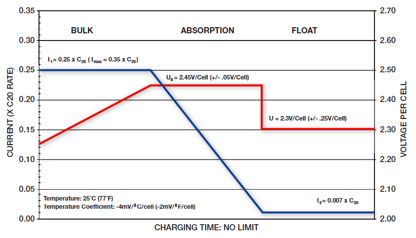
A 3-stage charger which can do both constant current bulk stage, and constant voltage absorb and float stages has a curve like you'll see in almost every battery manual as the "recommended charge profile". Usually looks something like this:
Whereas a constant voltage charger has a curve that looks like this:

dwh
Tail-End Charlie
Sanity check by request. <whips out totally awesome, gold plated, one time use, line item veto pen (black ink of course)>
Sized to carry the full output of the charger. For charging, distance isn't really an issue unless you start getting into serious distance, such as that 40 meters (!!) example of SmartGuage's. And really, if your charger is 20 meters away from your battery - you probably need to find a way to fix it (like maybe sticking a DC-DC charger in there somewhere).
"Undersized" is also a serious consideration. You can get away with it over short distances (auto manufacturers do it every day), but it will put a noticeable crimp in performance. Noticeable in the case of battery charging by taking a lot longer to charge, and in the case of supplying a load such as in inverter in having it shut down from low voltage when the battery still has plenty of voltage to run it.
And you can sometimes make undersized work for you. I recall you said you couldn't use a Sterling because of the 15.5v of your factory system. (I assume you meant a DC-DC charger rather than a Sterling piggy-back voltage regulator which would override your factory regulator anyway.) Well, the voltage is 15.5v peak under the hood. You might have been able to get away with a DC-DC charger in the back with the aux battery and undersized wire to feed it from the main bus - thereby using that handy "theoretical" voltage drop to shave that 15.5v down to a manageable level.
Of course, that would be what is known as a "hack", and the way you did it is better (proper), but in a pinch...there are some tricky ways to skin cats.
I'm curious as to what size the factory wiring is.
So far so good. I'd say that's one helluva rounding down though. But it works.
Okay, that's insane. (Hey, you asked for a SANITY check.) That's one of the false assumptions I mentioned earlier.
The charger doesn't see anything individual on the system - it only sees the complete system. Or, as I refer to it - "the bus".
In the case of your rig, it sees the main bus voltage until the IBS closes the solenoid and connects the aux bus to the main bus - thereby creating one big "main bus" - then the voltage regulator still sees the "main bus" voltage.
When the IBS connects the two into a single bus, the main bus voltage starts dropping and the aux bus voltage starts rising. The voltage regulator is going to see the *product* of that process.
<Time for the air pressure analogy...> The main air tank (main battery) is full and you open a valve to connect an aux air tank (aux battery). The overall pressure of the system drops, which triggers the pressure switch which turns on the compressor. The pressure switch don't know from jack what is happening where, it just knows the pressure is down.
Though actually, in the specific case of your rig, when the IBS opens the valve to the secondary tank, the main isn't full yet, because you ran it down a bit last night sipping merlot and gleefully converting gobs of watts into BTUs. So the switch that turns on the compressor has *already* tripped and the compressor is *already* running when you open the valve to connect the two tanks.
Now consider this: If the compressor is big enough to supply enough air, air will flow from it into *both* tanks, raising the pressure of the whole shooting match.
Which would shoot down what I see as another (possibly) dodgy assumption: That the chassis battery is feeding the aux battery when the IBS ties them together.
Of course, here the analogy breaks down a bit, since air tanks would equalize quickly and then the compressor would raise the whole system's pressure, but with lead-acid batteries it works a bit differently because they resist; so what happens is the voltage regulator sees a low voltage on the bus, turns on the alternator to supply the bus and whichever battery has a lower potential (both) than the alternator is going to get power flowing IN to it, rather than out of it.
In other words: IF the alternator were not large enough to supply all the AMPs the aux is drawing, then the aux would pull the bus voltage down below the voltage of the main battery, and THEN the main battery would start supplying power to the bus to make up the difference.
(That's what happens when you run a winch with a 200a load and you only have a 100a alternator. The bus voltage drops below the battery voltage, and the alternator can't prevent that, so power runs out of the main battery to the bus (in this case, at a rate of 100a).)
Well sorta. They use higher voltage *set points* because modern VRLA batteries can handle higher voltages. But that's the set points, not the flow control of the current.
The control of the current flow is a function of the *potential* voltage (until you hit the current limit). The higher the difference in *potential* the greater the flow rate, but the higher voltage itself doesn't actually exist until the battery gets there (reaches the set point), because the battery is limiting the voltage.
(Yes, that was pedantic, but since I'm here anyway... )
Critical in VRLA batteries. All sealed lead-acid batteries are VRLA. There are also flooded sealed batteries and they can't be topped up either.
<pedantic>
Any voltage regulated, alternator supplied vehicle bus is going to handle headlights and wipers (normal expected loads) because as soon as you turn 'em on, the bus voltage drops. And solid-state voltage regulators operate bloody fast to begin with. I think the shunt is just a way to allow a computer controlled setup to get a read on the amp flow.
Can't comment on the remote voltage sensor. Sounds good though - run with it.
Once again, I'm thinking dodgy assumption unless you've actually measured it happening. In which case, "Shut ma mouf!"
(Okay, now here's where it gets REALLY pedantic...)
Original poster? Original poster? ******? I though the original poster was evldave showing how to make a cheap isolator setup and the rest of us were just a bunch of drunks stumbling around in an off-topic daze!
Didn't I title my last post, "violent agreement"?
-- Electrical circuits are circuits. Agreed. This means that resistance on either leg can cause a voltage drop in the circuit. It is simply easier to imagine that it lies between point A and B.
-- The charging circuit must be wired to carry the full output of the charger over the distance between the charger and the battery. Agreed. (In my particular case, I simply accepted the GM factory wiring and took AM Solar's suggested wiring size for the solar kit.)
The crux of the issue, may be "oversized" vs. "right sized." Here too, I agree.
Sized to carry the full output of the charger. For charging, distance isn't really an issue unless you start getting into serious distance, such as that 40 meters (!!) example of SmartGuage's. And really, if your charger is 20 meters away from your battery - you probably need to find a way to fix it (like maybe sticking a DC-DC charger in there somewhere).
"Undersized" is also a serious consideration. You can get away with it over short distances (auto manufacturers do it every day), but it will put a noticeable crimp in performance. Noticeable in the case of battery charging by taking a lot longer to charge, and in the case of supplying a load such as in inverter in having it shut down from low voltage when the battery still has plenty of voltage to run it.
And you can sometimes make undersized work for you. I recall you said you couldn't use a Sterling because of the 15.5v of your factory system. (I assume you meant a DC-DC charger rather than a Sterling piggy-back voltage regulator which would override your factory regulator anyway.) Well, the voltage is 15.5v peak under the hood. You might have been able to get away with a DC-DC charger in the back with the aux battery and undersized wire to feed it from the main bus - thereby using that handy "theoretical" voltage drop to shave that 15.5v down to a manageable level.
Of course, that would be what is known as a "hack", and the way you did it is better (proper), but in a pinch...there are some tricky ways to skin cats.
In my case, I have a 300Ah starter battery bank connected to a pair of alternators with a combined specced output of 250A. I am using the GM factory wiring.
I'm curious as to what size the factory wiring is.
This 300Ah battery bank is connected to a 600Ah camper battery bank, about 20 linear feet away. (The actual cable length is probably closer to 25 feet, one way, call it 40-50feet, round trip.) I want to achieve the highest possible current flow between the two battery banks. Using Chris Gibson's formula as a guide (http://www.smartgauge.co.uk/cable_type.html) If I go for a voltage drop of 0.5, in the circuit, then I need 360mm2 of copper. I simply rounded this down to about 100mm2 which I get by using a pair of AWG 1/0 cables. Using a pair makes it easier to run, especially as each of my starter batteries is on a different side of the truck.
So, my, wiring is not "oversized" but rather only about 1/4 of the textbook size.
But, when you realize that 99% of all dual battery setups run cables between AWG 6 and 10, that is under 15mm2, it is "oversized" compared with industry practice, but, in fact, undersized for the potential amp flow over the distance required.
So far so good. I'd say that's one helluva rounding down though. But it works.
Some more agreement. A charger will only "see" the battery to which is it most closely connected.
Okay, that's insane. (Hey, you asked for a SANITY check.) That's one of the false assumptions I mentioned earlier.
The charger doesn't see anything individual on the system - it only sees the complete system. Or, as I refer to it - "the bus".
In the case of your rig, it sees the main bus voltage until the IBS closes the solenoid and connects the aux bus to the main bus - thereby creating one big "main bus" - then the voltage regulator still sees the "main bus" voltage.
When the IBS connects the two into a single bus, the main bus voltage starts dropping and the aux bus voltage starts rising. The voltage regulator is going to see the *product* of that process.
<Time for the air pressure analogy...> The main air tank (main battery) is full and you open a valve to connect an aux air tank (aux battery). The overall pressure of the system drops, which triggers the pressure switch which turns on the compressor. The pressure switch don't know from jack what is happening where, it just knows the pressure is down.
Though actually, in the specific case of your rig, when the IBS opens the valve to the secondary tank, the main isn't full yet, because you ran it down a bit last night sipping merlot and gleefully converting gobs of watts into BTUs. So the switch that turns on the compressor has *already* tripped and the compressor is *already* running when you open the valve to connect the two tanks.
Now consider this: If the compressor is big enough to supply enough air, air will flow from it into *both* tanks, raising the pressure of the whole shooting match.
Which would shoot down what I see as another (possibly) dodgy assumption: That the chassis battery is feeding the aux battery when the IBS ties them together.
Of course, here the analogy breaks down a bit, since air tanks would equalize quickly and then the compressor would raise the whole system's pressure, but with lead-acid batteries it works a bit differently because they resist; so what happens is the voltage regulator sees a low voltage on the bus, turns on the alternator to supply the bus and whichever battery has a lower potential (both) than the alternator is going to get power flowing IN to it, rather than out of it.
In other words: IF the alternator were not large enough to supply all the AMPs the aux is drawing, then the aux would pull the bus voltage down below the voltage of the main battery, and THEN the main battery would start supplying power to the bus to make up the difference.
(That's what happens when you run a winch with a 200a load and you only have a 100a alternator. The bus voltage drops below the battery voltage, and the alternator can't prevent that, so power runs out of the main battery to the bus (in this case, at a rate of 100a).)
In the case of lead acid batteries, the function is really rather simple. The charger monitors the voltage of the battery and, when it detects a drop, supplies current (amps) and voltage until it raises the voltage to the desired level. The more modern the charger, the more the bells and whistles and the better the charging function. Modern chargers:
-- Use higher voltages than before, as the higher voltage difference, the greater the current flow.
Well sorta. They use higher voltage *set points* because modern VRLA batteries can handle higher voltages. But that's the set points, not the flow control of the current.
The control of the current flow is a function of the *potential* voltage (until you hit the current limit). The higher the difference in *potential* the greater the flow rate, but the higher voltage itself doesn't actually exist until the battery gets there (reaches the set point), because the battery is limiting the voltage.
(Yes, that was pedantic, but since I'm here anyway...
)-- Use a multi stage program, typically bulk, absorb, float, to charge fast, charge deep (dissipate surface charge), and maintain.
-- To do this, modern chargers typically incorporate temperature sensing to raise voltage as the weather turns cold and, at the same time, avoid boiling off moisture in the battery. (Especially critical in gel and AGM batteries that cannot be topped up with water.)
Critical in VRLA batteries. All sealed lead-acid batteries are VRLA. There are also flooded sealed batteries and they can't be topped up either.
<pedantic>
They may also respond to specific needs like headlights or windshield wipers. Some also incorporate a shunt to more quickly respond to battery discharge and, in some cases, a remote voltage sensor to compensate for voltage loss in the circuit.
Any voltage regulated, alternator supplied vehicle bus is going to handle headlights and wipers (normal expected loads) because as soon as you turn 'em on, the bus voltage drops. And solid-state voltage regulators operate bloody fast to begin with. I think the shunt is just a way to allow a computer controlled setup to get a read on the amp flow.
Can't comment on the remote voltage sensor. Sounds good though - run with it.
So, how does the truck alternator/regulator side of my system work?
-- Start engine or let the sun rise, battery voltage rises to >13.2v. Relay closes.
-- At this point, the starter batteries and camper batteries are connected. Current flows from the more highly charged battery to the less charged battery.
Once again, I'm thinking dodgy assumption unless you've actually measured it happening. In which case, "Shut ma mouf!"
-- The rate of that flow is determined by the voltage difference and restricted by the resistance of the cabling.
-- Either or both chargers will respond to any voltage drop in their battery(s), by ramping up voltage and current, to the limits of the charger.
So, to go back to the original poster's system, what is the news you can use?
-- You need to know the size of the primary battery and the capacity of your charger.
-- Then you need to know the distance between the batteries. Both under the hood? You can probably use 15 feet, round trip. Back of your truck? You are probably guessing over 40 feet.
This known, you can calculate the size of the cabling required. This chart is probably close enough:
View attachment 238559
Where would I differ with the original poster? Only on this, if you have a solar kit, there are benefits to using an automatic, bidirectional relay, as opposed to a key controlled relay.
I'll buy you the beer, but you gotta buy me a decent Merlot.
[/COLOR]
(Okay, now here's where it gets REALLY pedantic...)
Original poster? Original poster? ******? I though the original poster was evldave showing how to make a cheap isolator setup and the rest of us were just a bunch of drunks stumbling around in an off-topic daze!
dwh
Tail-End Charlie
Once again, I find myself agreeing with dwh. (Perhaps because he does this for a living?)
In a past life.
"A long time ago in a galaxy far, far away..."
Similar threads
- Replies
- 7
- Views
- 1K
- Replies
- 0
- Views
- 197
- Replies
- 11
- Views
- 2K
- Replies
- 3
- Views
- 485