I do some composite failure analysis as part of my day job. Part of this is interfacing composite parts with traditional metal structures. I can say with certainty that many failure modes are not intuitive, even to engineers with classical training. Load transfer is also highly dependent on the composite panels stiffness in each loading direction. Paying for good engineering is often worth the cost. Unfortunately this isn't an area where you can just do a high level copy of something that "works". The first step in a decent design is good data on the composite panels. This includes the stiffness (modulus), allowable strain in each loading type, thermal expansion characteristics, and concentrated load allowables. Once you start asking, you will find many composite panel suppliers do not have most, or any of this data. Ideally from actual qualification testing, but conservative numbers from basic calculations can substitute.
All that said, adding additional material (increasing the stiffness) of an attached metal structure can be counter productive, resulting in higher peak/concentrated loads. This isn't something I would want some recent engineering grad working on, thats for sure! In fact its often best to design a attachment with weak points. Better to have a bolt shear or fail in tension, then have a composite panel fail in buckling or pure bending. Of course the failure modes need evaluated for safety.
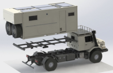
Depending on the stiffness of the box/composite, and its allowable ultimate loads, a subframe can be made quite light. Say a 14ft box in the 5,000-7,000lb range could be less than 400lbs. In these cases the subframe serves as a locator, and it spreads out loads. With the box itself providing the vast majority of the structure. This is the most efficient way, as a good composite panel will have much higher specific stiffness.