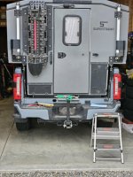
Supertramp Flagship LT pop-up slide-in pickup camper

Chadx

♫ Offroad, again. Just can't wait to get...♫
I don't recall if I posted this STC video previously, but still one of their best comprehensive system walk throughs and Matt always does a great job. Held up quite well over the last 10 months, though there are some additional options since this was releases (like the Victron battery options for anything over 200Ah of battery and can be sized up to 800Ah).

One can find their other videos here: https://www.youtube.com/@supertrampcampers2223/videos


roamie

New member
@roamie Went back to some of your previous posts and and guessing you have the Victron batteries. If so, then they have external battery heaters and power consumption that would be tracked by the shunt (the load you see when everything else is off and battery heaters are on) unlike the Battleborn and other brands that have internal heaters and power consumption that is not tracked by the shunt. If so, ignore all the internal heater comments above but I'll leave that info as it applies to those with Battleborn with internal heaters.
Yep that's correct, I have the Victron batteries. And yeah, my understanding is the trade off in size for the battery capacity was that the heaters were moved to be external. I actually don't remember turning the battery heaters on, so I think it must have been switched on when I picked it up.

I'm going to try turning off the battery heater and seeing what the discharge is on the system. It's not really a big deal to turn off the fuse block and main breakers since I'm already having to turn off the actuator switches, but I wouldn't expect there to be much drain with everything off.
 

roamie

New member
With the battery heaters turned off, the constant drain right now is around -0.6A. Much more in line with what I'd expect. From their website, Supertramp said the Battle Born heater pulls 3A per hour at max heat, so I'm surprised the Victron pull is as high as it is. It's not even that cold here, between 45-60 degrees. But turning off the battery heater is the only change I made, I didn't turn off any of the fuse blocks.
 

Chadx

♫ Offroad, again. Just can't wait to get...♫
With the battery heaters turned off, the constant drain right now is around -0.6A. Much more in line with what I'd expect. From their website, Supertramp said the Battle Born heater pulls 3A per hour at max heat, so I'm surprised the Victron pull is as high as it is. It's not even that cold here, between 45-60 degrees. But turning off the battery heater is the only change I made, I didn't turn off any of the fuse blocks.

STC estimate sounds about right. Battleborn says there heater draws 1.8A when active, so that would be 3.6A for the typical STC which has two 100Ah batteries. Internal battery heaters are much more efficient per watt because they are within the battery housing. With the Victron batteries, the heating pads are much larger and external so they have to be much higher wattage to heat up the cells within the battery housing. When I saw the Victron setup for 400Ah (two 200Ah victron batteries), heating pads covered the entire front and back of the batteries, so 9" x 24" heating pads times two. I can see that drawing a fair bit considering the surface area compared to the small internal heaters.

It does seem odd that they are triggering when your lows are only 45F. Not sure where the thermostat is located on these heating pads. If external, it would have to deal with a lot of variables including the toughest, which is a below freezing cabin/battery that has recently been heated up by Truma heater. The battery itself would still be below 40F. The battery protect would not allow charging due to the internal cell temp sensor, but if the pads were controlled by an external sensor, it wouldn't know so functionally it would make sense to turn it on a warmer temps. Now you have me curious if the external heating pads are triggered by external sensor or somehow communicate with the Victron BMS. I've reached out to STC and will report back.
 
Last edited:

Chadx

♫ Offroad, again. Just can't wait to get...♫
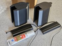
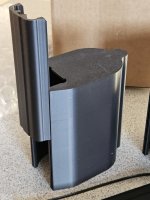
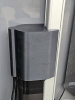
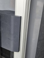
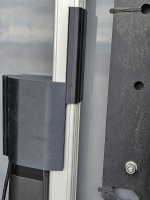
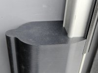
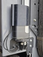
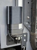
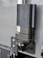
External actuator shrouds arrived this morning. This is the first phase of a two-phase Supertramp actuator solution. I plan to install prior to our rainy trip, this coming weekend, to chase Tamarack color change.

20251025_110505.jpg

20251025_110852.jpg
 
Last edited:

SimplyAnAdventure

Well-known member
I haven’t seen mine yet and I’m pretty sure my camper was made before yours…. I must not be on the list.

I’m about done for the year anyway and my camper stays indoors in a climate controlled garage all year so I’m not too worried about it either way.

Definitely looking forward to see how they work out.
 

Chadx

♫ Offroad, again. Just can't wait to get...♫
Might simply be mailing time. MT and CO has shorter USPS time than to east.

Finished chores for the day so heading out to install now.
 

SimplyAnAdventure

Well-known member
Might simply be mailing time. MT and CO has shorter USPS time than to east.

Finished chores for the day so heading out to install now.
I was kind of just being snarky lol. They reported that they made 50 of them and I’m 73 so I assumed mine wouldn’t be in the first batch anyway.
 

Chadx

♫ Offroad, again. Just can't wait to get...♫
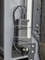
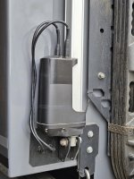
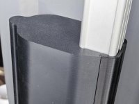
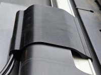
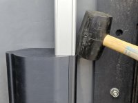
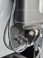
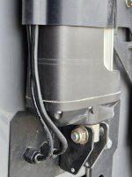
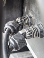
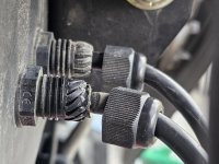
All done. Was pretty straight forward. Instructions are good. The parts look to be 3D printed. Takes some finesse to get the main part over the square actuator tube as I was scared to crack them. Went fine, though. The two sections slot together and are a tight fit, but using the recommended rubber mallet to slowly and lightly tap the narrow piece down in the main piece worked well. Just be sure they are aligned and started before tapping. The cables end up with some extra slack, but you can loosen the four cable glands and push the slack into the camper.

20251025_125542.jpg20251025_125632.jpg20251025_125943.jpg20251025_125948.jpg20251025_130056.jpg20251025_130107.jpg20251025_130257.jpg20251025_130332.jpg20251025_130342.jpg20251025_132350.jpg
 

Chadx

♫ Offroad, again. Just can't wait to get...♫
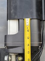
Both my covers ended up about 3.5" from the gasket. I measured to ensure they sat uniform between the two.

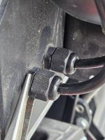
If you unscrew the cable glands to push in slack cable, ensure you are only unscrewing the gland cap. When I started unscrewing the cab, the gland nut itself started to unscrew on one particularly tight one and that unscrews from an internal part, which you do not want to do.

Using a needlenose pliers to hold the gland nut itself did the trick (wrench was too thick and blocked unscrewing the cap which also has a hex edge on it). Of note, on one of my glands, the inner rubber ring, that is supposed to be pushed well inside the fingers, hadn't been inserted all the way. I worked it back in so the fingers and cap can do their thing when tightened back down.

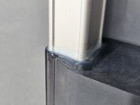
My silicon job was not the best, but I just ran the bead, did the wipe, then tried to clean up excess the best I could (pic below is before I wiped off excess). Seems very sealed up and if one ever had to remove it, removing the small section of silicon is all that is needed.

I think I like the look even better than the original is it hides upper actuator cabling and plugs.
Now I just need to get them dusty so the blend in better with the rest of the black stuff hanging off the back. Ha.


20251025_131517.jpg

20251025_130810.jpg

20251025_131140.jpg

20251025_132421.jpg

20251025_130403.jpg

20251025_130801.jpg

20251025_133409.jpg

20251025_133552.jpg

20251025_133601.jpg

20251025_133620.jpg
 
Last edited:

SimplyAnAdventure

Well-known member
Both my covers ended up about 3.5" from the gasket. I measured to ensure they sat uniform between the two.

If you unscrew the cable glands to push in slack cable, ensure you are only unscrewing the gland cap. When I started unscrewing the cab, the gland nut itself started to unscrew on one particularly tight one and that unscrews from an internal part, which you do not want to do.

Using a needlenose pliers to hold the gland nut itself did the trick (wrench was too thick and blocked unscrewing the cap which also has a hex edge on it). Of note, on one of my glands, the inner rubber ring, that is supposed to be pushed well inside the fingers, hadn't been inserted all the way. I worked it back in so the fingers and cap can do their thing when tightened back down.

My silicon job was not the best, but I just ran the bead, did the wipe, then tried to clean up excess the best I could (pic below is before I wiped off excess). Seems very sealed up and if one ever had to remove it, removing the small section of silicon is all that is needed.

I think I like the look even better than the original is it hides upper actuator cabling and plugs.
Now I just need to get them dusty so the blend in better with the rest of the black stuff hanging off the back. Ha.


View attachment 899612

View attachment 899614

View attachment 899615

View attachment 899616

View attachment 899617

View attachment 899618

View attachment 899619

View attachment 899620

View attachment 899621

View attachment 899622
Great tutorial. Glad you got yours first 😉
 

roamie

New member
Both my covers ended up about 3.5" from the gasket. I measured to ensure they sat uniform between the two.

If you unscrew the cable glands to push in slack cable, ensure you are only unscrewing the gland cap. When I started unscrewing the cab, the gland nut itself started to unscrew on one particularly tight one and that unscrews from an internal part, which you do not want to do.

Using a needlenose pliers to hold the gland nut itself did the trick (wrench was too thick and blocked unscrewing the cap which also has a hex edge on it). Of note, on one of my glands, the inner rubber ring, that is supposed to be pushed well inside the fingers, hadn't been inserted all the way. I worked it back in so the fingers and cap can do their thing when tightened back down.

My silicon job was not the best, but I just ran the bead, did the wipe, then tried to clean up excess the best I could (pic below is before I wiped off excess). Seems very sealed up and if one ever had to remove it, removing the small section of silicon is all that is needed.

I think I like the look even better than the original is it hides upper actuator cabling and plugs.
Now I just need to get them dusty so the blend in better with the rest of the black stuff hanging off the back. Ha.


View attachment 899612

View attachment 899614

View attachment 899615

View attachment 899616

View attachment 899617

View attachment 899618

View attachment 899619

View attachment 899620

View attachment 899621

View attachment 899622
Great instructions, and I agree it does look better overall.

Question though, why do you end up with extra slack in the cabling compared to the original install? It looks like you could even leave the existing bottom zip tie where it is.
 

Chadx

♫ Offroad, again. Just can't wait to get...♫
...
Question though, why do you end up with extra slack in the cabling compared to the original install? It looks like you could even leave the existing bottom zip tie where it is.

Without the cover, the cables rise up from the top of the actuators fairly far. When you slide down the cover, you slowly press downward, while easing the cables down the side channel, to seat the cover a bit lower and curving the top loop of the cables sooner. This results in what seemed like 2" - 3" more cable down near the cable glands which is why I loosened the cable glands and pushed in some of the excess cable. That is noted in the STC instructions as an optional step.
 

Chadx

♫ Offroad, again. Just can't wait to get...♫
STC estimate sounds about right. Battleborn says there heater draws 1.8A when active, so that would be 3.6A for the typical STC which has two 100Ah batteries. Internal battery heaters are much more efficient per watt because they are within the battery housing. With the Victron batteries, the heating pads are much larger and external so they have to be much higher wattage to heat up the cells within the battery housing. When I saw the Victron setup for 400Ah (two 200Ah victron batteries), heating pads covered the entire front and back of the batteries, so 9" x 24" heating pads times two. I can see that drawing a fair bit considering the surface area compared to the small internal heaters.

It does seem odd that they are triggering when your lows are only 45F. Not sure where the thermostat is located on these heating pads. If external, it would have to deal with a lot of variables including the toughest, which is a below freezing cabin/battery that has recently been heated up by Truma heater. The battery itself would still be below 40F. The battery protect would not allow charging due to the internal cell temp sensor, but if the pads were controlled by an external sensor, it wouldn't know so functionally it would make sense to turn it on a warmer temps. Now you have me curious if the external heating pads are triggered by external sensor or somehow communicate with the Victron BMS. I've reached out to STC and will report back.

@roamie STC provided some more info on the heat pads used with the Victron battery solution.

As previously discussed, since Victron batteries don't have internal heater so external heat pads are used. STC shared that the heat pads watt/amp draw is 78W/5.8A for a 400Ah Victron battery bank (2 x 200Ah batteries). When the Battery Heater switch is on, the battery heat pad thermostat turns on when temp dips to 44F and turns off at 68F. The heat pad thermostat is measuring ambient temperature within the battery compartment and is not communicating directly with the Victron BMS nor internal Victron battery temp sensors. In order for the battery pads to communicate with the Victron internal sensors, a good deal more equipment would be needed including the Victron Servo system. Per the Victron rep, they have never had a customer experience issues using heat pads set up this way and they shared that the batteries are compact enough that the heating pads heat them up quickly, thus avoiding a large temperature delta between compartment temps and internal battery temps. And, STC has the Victron batteries programmed to not accept charge below 33F, so even if there was a delta, the batteries themselves would not accept charge until they were above that set temp.

A perk of external battery heater pads, vs internal battery heaters, is the draw is known to the shunt so you can see when the heat pads are drawing power. And, the Battery Monitor knows about the draw so your SOC will remain accurate. When batteries have internal heat pads, the power draw is not known to the shunt, so the battery monitor SOC does not decrease even though power is being consumed by the internal heat pads and cell SOC is decreasing.

I like external battery heater setups better as you are more aware of what is happening, SOC stays accurate, etc. And, you can always turn off the battery heater switch if you know batteries are above freezing (you've had cabin heat above freezing for a good period of time) and you are charging them. Or, when they are below freezing but you will not be charging them. No reason to have Battery Heater switch turned on in those situations.

Now, to digress and discuss batteries with internal heat. Different batteries use different methods to power internal heat pads. Last I checked, Battleborn uses the following method; the heat pads are powered only by battery cells. That allows the battery to be heated even if there is no incoming charge current. That is good if you want to preheat the batteries before a charge current in applied. Such as, before sun comes up for solar charging, to pre-heat before starting truck for DC charging, or before shore power charging is connected. The con is if you turn on battery heat and forget about it, it will run down your battery fairly low before it disconnects. Then you have a discharged battery bank. And, your battery monitor doesn't know about the draw, so it reports the same SOC from when you turned on the battery heat. This can be a unpleasant surprise if you trust the SOC when using internal battery heaters.

Some other brand batteries, with internal heaters, can only power internal heaters if there is charge input and it uses only that charge input to power the internal heat pads. Usually there is a minimum charge input, like 10A per 12v battery. The battery monitor will also be inaccurate with this method because the shunt thinks the inbound charge power is charging the battery, but all the inbound power is going to the heat pads. Note that no matter how much current is available, only the current that the heating pads use passes through the shunt and into the battery. Meaning, if you have a 50amp charge source, only what the internal heat pads use will be used. Such as 10A of the 50A available. No current is charging the battery until the BMS determines the cells are warmed up enough. Then the battery can start to charge, but heat pads remain on. So it will start using all 50A if the charger source, but only 40A is going to charge battery because 10A is still going to internal heater. Once heater turns off, all 50A can go to charge battery. However much current the heat pad used, that is how far off the Battery Monitor SOC will be.

Example: A 100Ah battery uses 10A for internal heater. It's at 50% SOC. You turn on heat pad and turn on a 20Amp charge source. If it takes exactly 1 hour to heat battery cells to adequate charging temp, the charge will have output 10A, the shunt knows that 10A went across it, but does not know that it went to internal heater rather than battery cells. Battery monitor will report that the battery SOC is now 60% SOC, but it's still only 50% SOC because all 10Amps when to the heat pad. At the end of the first hour, the cells are warm enough to take charge, the full 20amp charge goes through the shunt, but 10A is still being burned by internal heat pads, and the other 10A is charging cells. If this situation lasts exactly one hour, the battery monitor will now report the battery is at 80% SOC (reading goes from an incorrect 60% and increases by another 20% when the battery only went up 10A, so the real SOC has now moved from the real 50% to a real 60%. If the battery heater now turns off and 20amp charge rater another hour, both the battery monitors SOC and the real SOC goes up 20A (20% in this case). Battery monitor will inaccurately report 100%, but real SOC is now 80%. If you think it's at 100% and remove charge, you'll only be at 80%. The point is, when using internal battery heaters, the battery monitors SOC reading will not be accurate again until you charge to true 100% SOC. Not when the battery monitor reaches 100% SOC, because that will be inaccurate. But charged until the charger shuts off because voltage set point (typically 14.4v - 14.6v) is reached and current tapers off. Then SOC will be accurate again (until the next time internal battery heat pads are used). External heat pads have the advantage if an accurate SOC is important to you.

While I'm off on internal battery heaters, some batteries allow you to choose heat pad power source within their app and some have a third method of powering internal heaters; hybrid source. I've used batteries where you can set them to hybrid mode so, if the inbound current is not adequate to run the internal heaters, the remaining needed current will draw from the battery cells. Meaning, if they need 10A but inbound charge current is only 4A, the remaining 6A will come from battery cells to provide the needed 10A. If there is 25A of available inbound charger current, the internal heats pads will get 100% of the needed 10A current from the available inbound current. Only the needed heat pad current will be used and the remaining available current will go unused until the battery cells are warmed up and can start using all the inbound current to charge the battery cells. These same batteries allowed you to choose a standard method of internal heat that will use only current from the battery, but I always left them on the hybrid because if there was any inbound charge current available, I wanted the heaters to prioritize using that source and then fill in the remainder with battery power.
 
Last edited:

Forum statistics

Threads
190,624
Messages
2,929,731
Members
234,294
Latest member
Joseph McCormack
Top