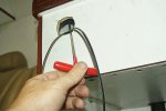
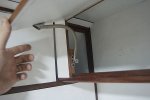
One of the other things I did on the interior is find and fit the stays for the overhead locker doors. The cabinet maker said he had heard from a friend about a type of spring latch at Whitworths Marine supplies, so I went down there and had a look. This is what I found, and they work great,.
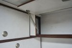
The spring stays straight, and is strong enough to hold up the door easily. To close the door, all you need to do is bend the spring, and you can close the lid. All pretty easy. It has taken about a year to find a solution for this, and to find something so simple that just works is great.
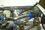
With all the intercooler stuff sorted out, it was time to install the fuel filters and get the all the hoses sorted. New hoses, fittings and seals and a bit of red engine paint and there was another thing finished. I still have to fit the rest of the fuel lines to and from the tank, but it's a good feeling to fit something for the last time.
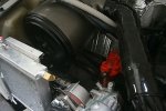
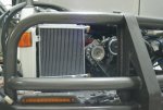
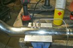
Next on the list was to paint up and fit the intercooler heat exchanger, with all the ports and fittings. It's great to be fitting things with the intention of not having to take them off again

.
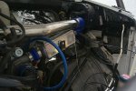
Since the heat exchanger is mounted on the chassis, and not the engine, I had to have a flexible coupling for the connection, I am not sure how much the engine moves, you can;t even move it a millimeter by hand, but I have positioned the coupling so that I have about 10mm of movement in and out. Hopefully this is enough, but time will tell.
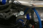
One of the most time consuming things this month has been designing and fabricating the heating system for the camper. It is pretty complicated, and getting the hot water all the way from either the engine or the Webasto 90ST diesel furnace. The camper hydronic system as it is called need to have different circuits. It has two operating modes. First off when the engine is running, the engine supplies hot water to camper hot water circuit. Since the engine driven water pump will pump into the cab heater, and also provides cooling for the turbo. The shear length of the camper hydronic circuit means that I am not sure if the engine pump will provide enough flow to go through the pipework. In order to ensure there is water flowing through the camper circuit I decide to use a Davies Craig electric water pump ( Just the little 15l/min booster pump). This means that the standard coolant loop remains in place, but the EWP will provide flow into the camper loop.
When the engine is switched off, then the diesel furnace supplies hot water to the camper circuit, but that has a built in water pump. The return flow will also heat up the engine block as well. The ST90 is a 9kw heater, so would have no problem keeping the block and the camper warm as well.
Inside the camper hot water circuit there are three loops. First is the calorifier, which is the primary loop and will always have coolant flowing through it, the secondary loop is the camper heater circuit, which will take priority over the calorifier by using 19mm pipe vs the 15mm pipe on the calorifier circuit. The third loop is for heating the rear compartment where the water tanks are - just to stop them freezing when we are in Siberia It will be also in parallel but with an 8mm ball valve to restrict flow as it just needs enough to keep temperature in the back above freezing so the water tanks don't freeze.
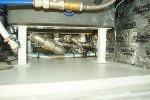
I decided to make the manifold out of stainless steel. I found a place called Sterling Australia and they sell stainless steel at reasonable prices. After much designing and figuring, I went and bought all the fittings. The next thing was to get make up the manifold. I bought a pipe threader off ebay, it cost $60 so I was not expecting much, but it was a piece of junk, and could only do one thread on the pipe before breaking. I tried to get another one, tried all the hardware stores, engineering supplies and and trade tool shops, eventually I even tried the hire shops, but no one had one. I eventually contacted the suppliers directly, but Rigid Tools did not have one that could do steel or stainless in stock. It would be a four week wait to get one from the US. It seems there is just no call for them in these days of plastic and copper pipe for all water plumbing.
In the end, I contacted the local engineering workshop, and after chatting to the foreman, he found, hidden in their back room, some dies that they have not used in years that could put a thread on the stainless pipe.
In order to get the lengths of the custom pipe correct, I decided to make up all the lengths of each individual pipe using 19mm plastic conduit, this way I could have a hope of getting things correct. I picked up the pipe late this afternoon, so will find out soon whether I am able to build something with millimeter tolerence or not.
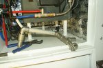
The final success story for the week is the control system for the electric air compressor. Like all things, the system is complex. The main engine driven air compressor will handle most of the load, but during start up, I need to boost the air supply, as the truck will not move until there is enough air pressure in the tanks to release the park brake. The electric ARB compressor puts out about the same amount of air as the engine compressor. The big difference is that when the air system gets up to operating pressure of around 8.5 Bar, the unloaded valve opens and the compressor freewheels down to around 7.5Bar.
The ARB compressor need to charge the system up to 7.5Bar, then switch off, and only come back on when the pressure is below 7.0Bar. The pressure warning light on mine comes on at 6.5Bar, so I need to keep the pressure above that.
A simple pressure switch would be ideal, but things are never simple. I got a pressure switch that closes at 7.0Bar, but there was quite a wide difference between switching on and off, around 2 Bar, which means it doesn't work. for what I want. I contacted Air Brake Systems and they came up with this solution. It is called a Bendix D2 Governor valve. It is part of a truck air brake system, so is build to last. The D2 is also adjustable, so after a bit of adjustment, it comes on at 7.5Bar and goes off at 7.0Bar, perfect.
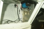
The is a bit more plumbing involved, as since there are two compressor, I had to add some non-return valves into the supply lines of each compressor, so that the when either one is not running, the air would not leak out of the other compressor. All of the components I got from Air Brake Systems to ensure they are meant for use in a truck air systems, not just relying on the ARB's cheap little non return valve. I tested the ARB and D2 today, and everything seems to work fine, it cuts in and out like it is supposed to do. Whats more, the ARB compressor by itself can get the system up to pressure in the mandatory 5 minutes required by the Australia regulations. Once I start the engine, I will be able to see if I got it all right.
The final thing today was to clean out the right hand fuel tank, and start working on the fuel system. I was surprised by the amount of dirt, bits of wood, metal shavings and sand in the fuel tank, but sloshing around 10 litres of diesel and I think I was able to get most of it out. I then rigged an electric pump to circulate the diesel through a CAV filter between the tank and a bucket. At the end of the day no dirt was coming out of the tank, so I put in another 10 litres of diesel and left the pump to circulate the fuel around the tank through the fuel filter for anther hour or so whilst I cleaned up the workshop ready for next week, where maybe I will get the engine running for the first time in 4 years.
 It is comfortable for us. We did consider making the locker around the top of the bed shorter, so that we could extended the head or foot room by the 100mm of so, but felt is was not necessary. A taller person might find it a bit short, but then we don't plan on having a taller person share the bed with us

