You are using an out of date browser. It may not display this or other websites correctly.
You should upgrade or use an alternative browser.
You should upgrade or use an alternative browser.
Rango.....1942 Willys MB
- Thread starter Metcalf
- Start date
jeepdreamer
Expedition Leader
Uh-oh... you should feed it, give it a bath, and send it away (to me).. quick! Its easier to do before you become to attached to them! 
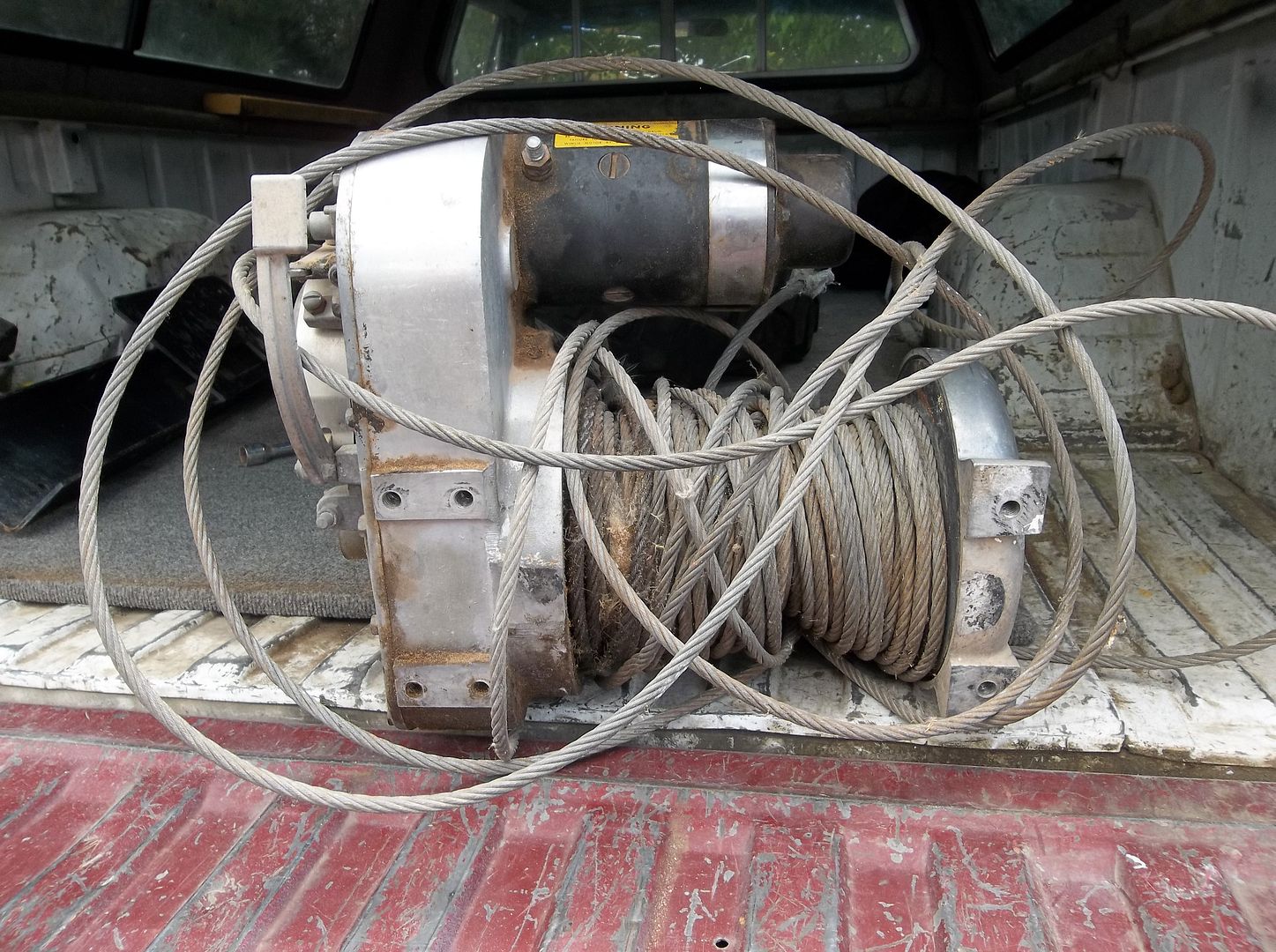
Nice find....Best winch out there IMHO! I'm guessing you won't leave that alone either so check these guys out. Crazy!
http://gigglepin4x4-shop.co.uk/
Nice find....Best winch out there IMHO! I'm guessing you won't leave that alone either so check these guys out. Crazy!
http://gigglepin4x4-shop.co.uk/
Metcalf
Expedition Leader
I couldn't probably ship it for less than I paid for it :sombrero:
Yes, it will get some mods....geeeesssss....you guys think I modify everything don't you!
Disc brake probably with some kind of auto and manual control system.
two way motor mod using a ramsey 8000lb motor as a base
upgrade to metal bushings or bearings
Probably about 125-150 feet of synthetic line
Custom aluminum hawse for the odd mounting pattern
drain plug
breather
etc etc
You know, just the basics :elkgrin:
I am also going to try to integrate the control cables into the dash perhaps so it looks like a factory application.
jeepdreamer
Expedition Leader
You?? Modify?? hahahaha! I think at the least I will add the motor upgrade and do away with the PITA solinoid packs in favor of the HD Relay deal. And prob. go synthetic as well...?
Metcalf
Expedition Leader
Saturday morning was body mount time....
I decided to make some simple mounts out of some of the same 2x4 box tubing as the most of the frame. Its handy when you have scraps around. I only bought 2 sticks of material and have had plenty to do everything so far. The main frame, rear crossmember, rear 'bumper', and front bumper. That really helps keep the cost of the frame down.
Anyways.....how to build simple body mounts.
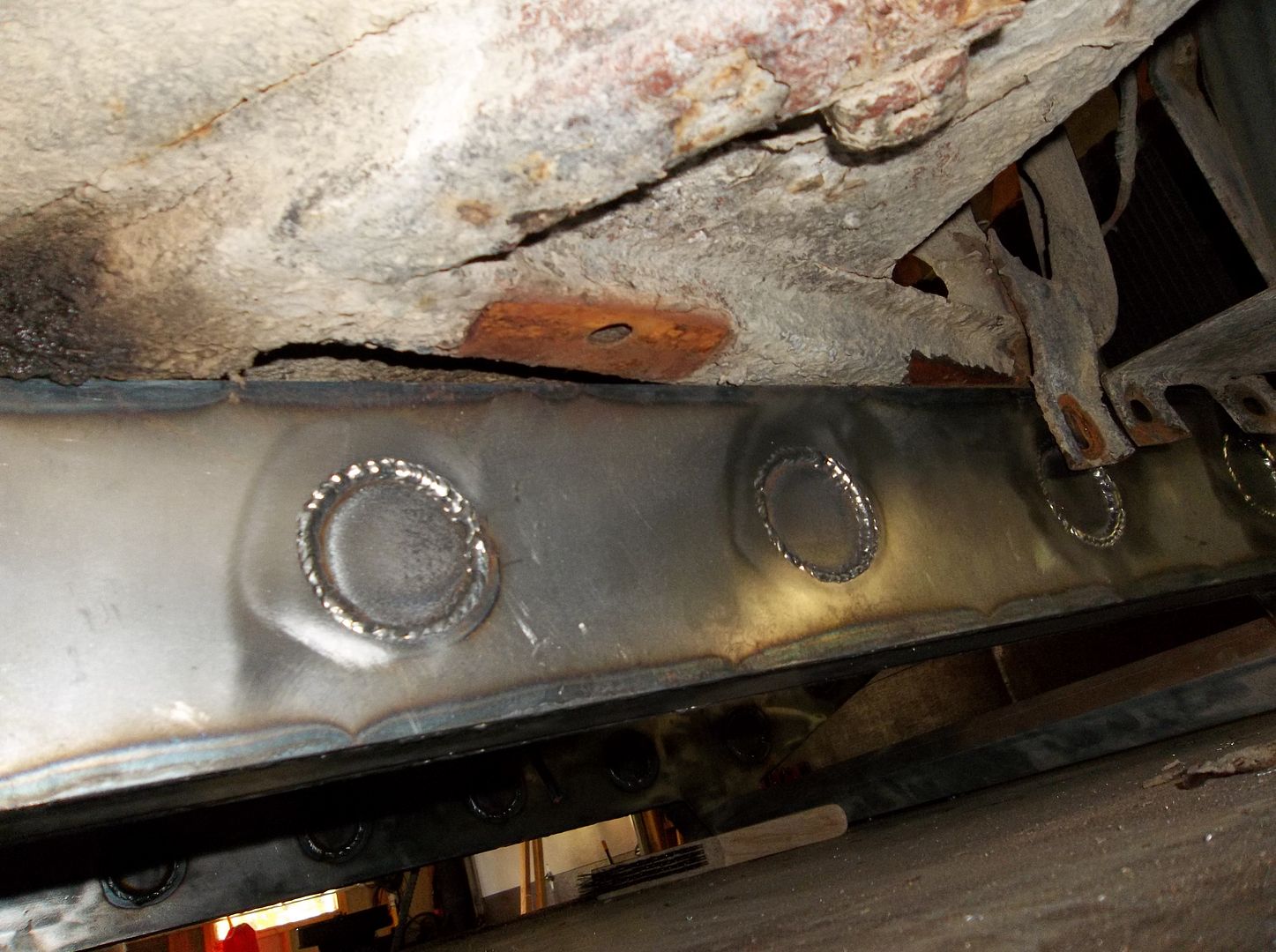
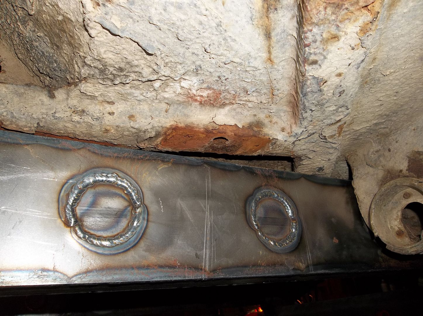
These two mounts are the only two mounts that are paired to be outside the frame on an MB body ( pad style ). I used these two to start the process since I could align the tub to the frame somewhat with these two mounts....
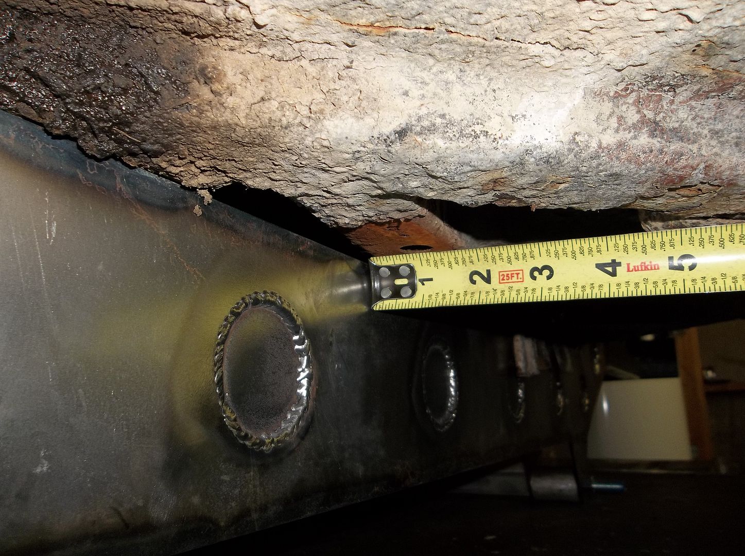
Measure, move the tub, measure, measure. These mounts ended up at an average of 7/8-15/16th away from the side of the frame. Once you get the offset number its pretty simple to build a pair of mounts....
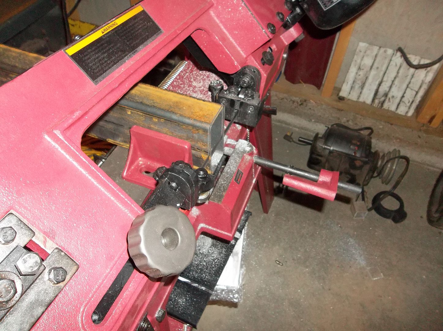
The first thing I generally do is square off the end of the scrap of tubing after doing a quick check for square on my might saw! This will make sure that the end of the tubing is square and a good place to start from....
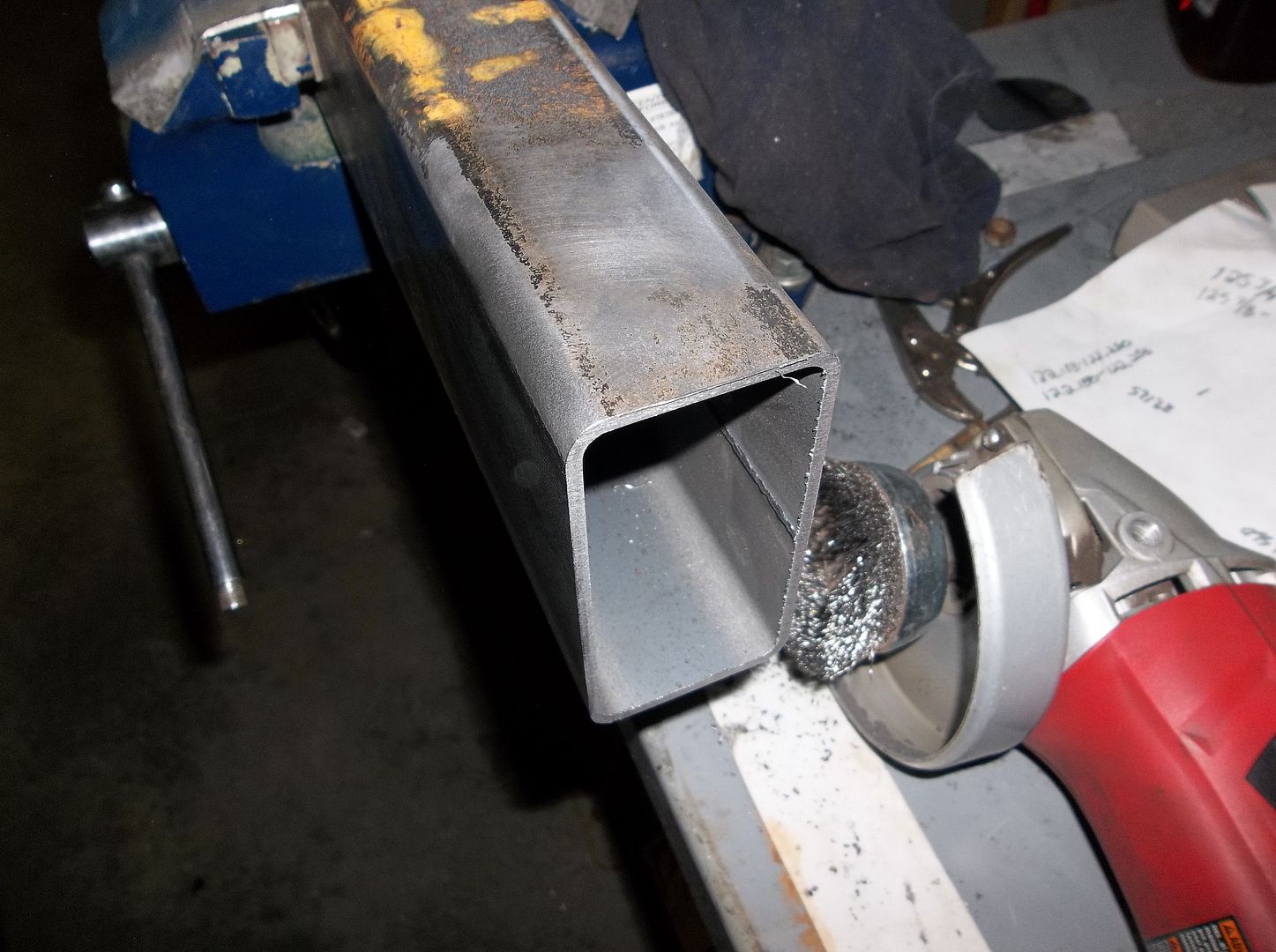
Then I run a wire brush over the area I am going to be marking on....
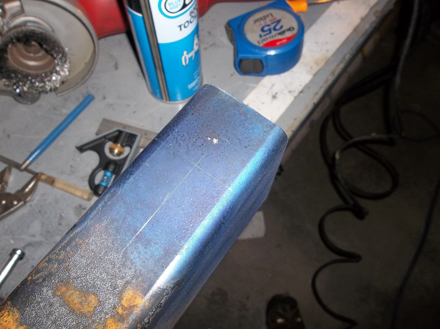
Then I spray the end in blue marking paint and scribe in all the information I need. I use a scribe for this since it seems to help eliminate compound tolerance errors. You get a tiny bit off with the marking, then a tiny bit off with the center punch, then a tiny bit off drilling, then a tiny bit off with the saw. Starting with a scribe line seems to keep this to 1/16-1/8 in the end for me.
I decided to make some simple mounts out of some of the same 2x4 box tubing as the most of the frame. Its handy when you have scraps around. I only bought 2 sticks of material and have had plenty to do everything so far. The main frame, rear crossmember, rear 'bumper', and front bumper. That really helps keep the cost of the frame down.
Anyways.....how to build simple body mounts.


These two mounts are the only two mounts that are paired to be outside the frame on an MB body ( pad style ). I used these two to start the process since I could align the tub to the frame somewhat with these two mounts....

Measure, move the tub, measure, measure. These mounts ended up at an average of 7/8-15/16th away from the side of the frame. Once you get the offset number its pretty simple to build a pair of mounts....

The first thing I generally do is square off the end of the scrap of tubing after doing a quick check for square on my might saw! This will make sure that the end of the tubing is square and a good place to start from....

Then I run a wire brush over the area I am going to be marking on....

Then I spray the end in blue marking paint and scribe in all the information I need. I use a scribe for this since it seems to help eliminate compound tolerance errors. You get a tiny bit off with the marking, then a tiny bit off with the center punch, then a tiny bit off drilling, then a tiny bit off with the saw. Starting with a scribe line seems to keep this to 1/16-1/8 in the end for me.
Metcalf
Expedition Leader
More.....had to cut the last post short while the computer did an update...
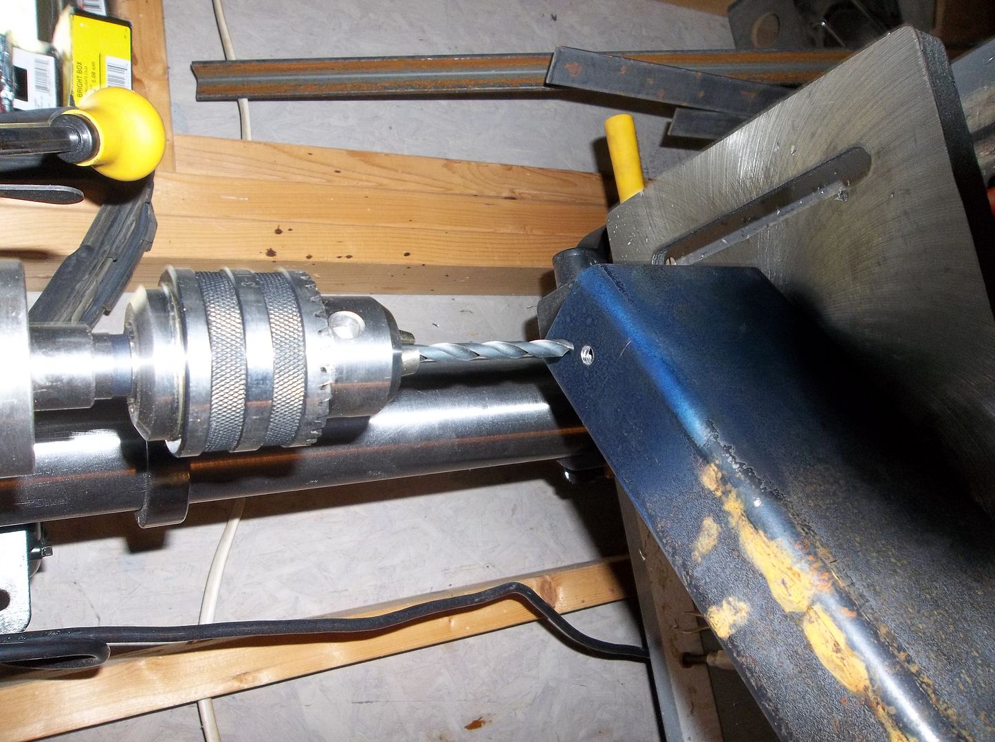
Next I drill out whatever holes I can while the part is whole on my monster expensive fancy drill press. I always try and drill in steps. These holes where going to be 1/2" in the end so I started with a 1/4" hole as a pilot after center punching the location.
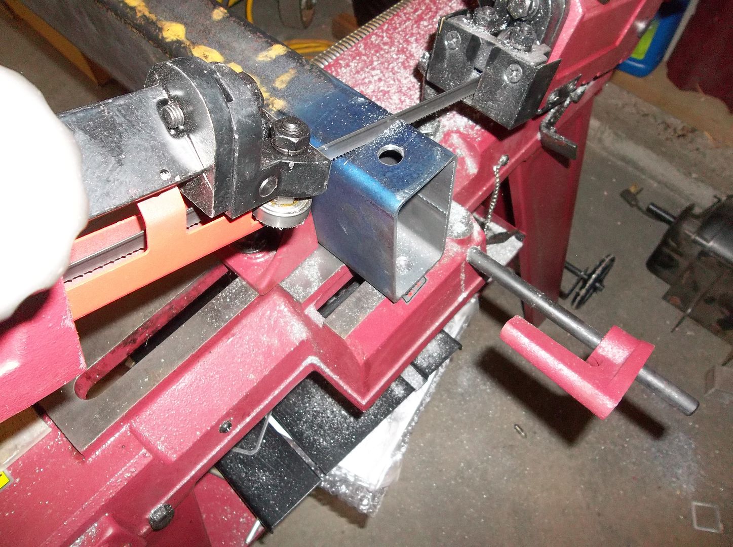
The part is then cut to length on the saw. Note: these little saws, all joke aside, are SUPER handy to have around for the garage fabricator!
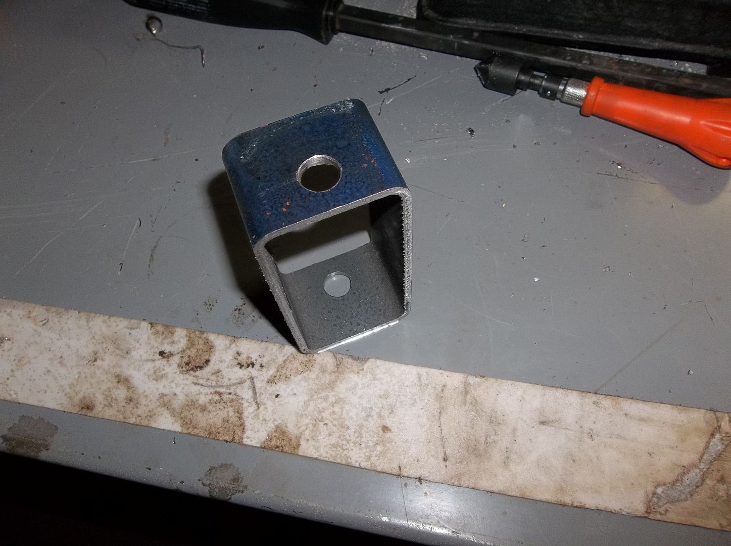
This is what you end up with. That doesn't look like much of a body mount, and wait, you drilled TWO holes in it. That just looks stupid.....
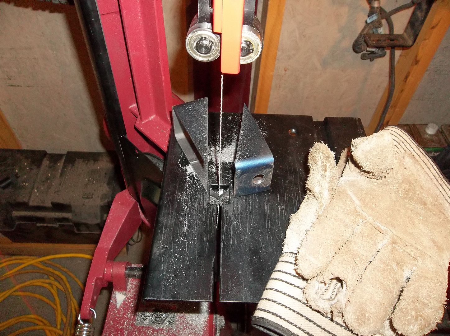
After a 30 second or less saw conversion I cut the mount into two parts. OHHHHHHH....it's two mounts
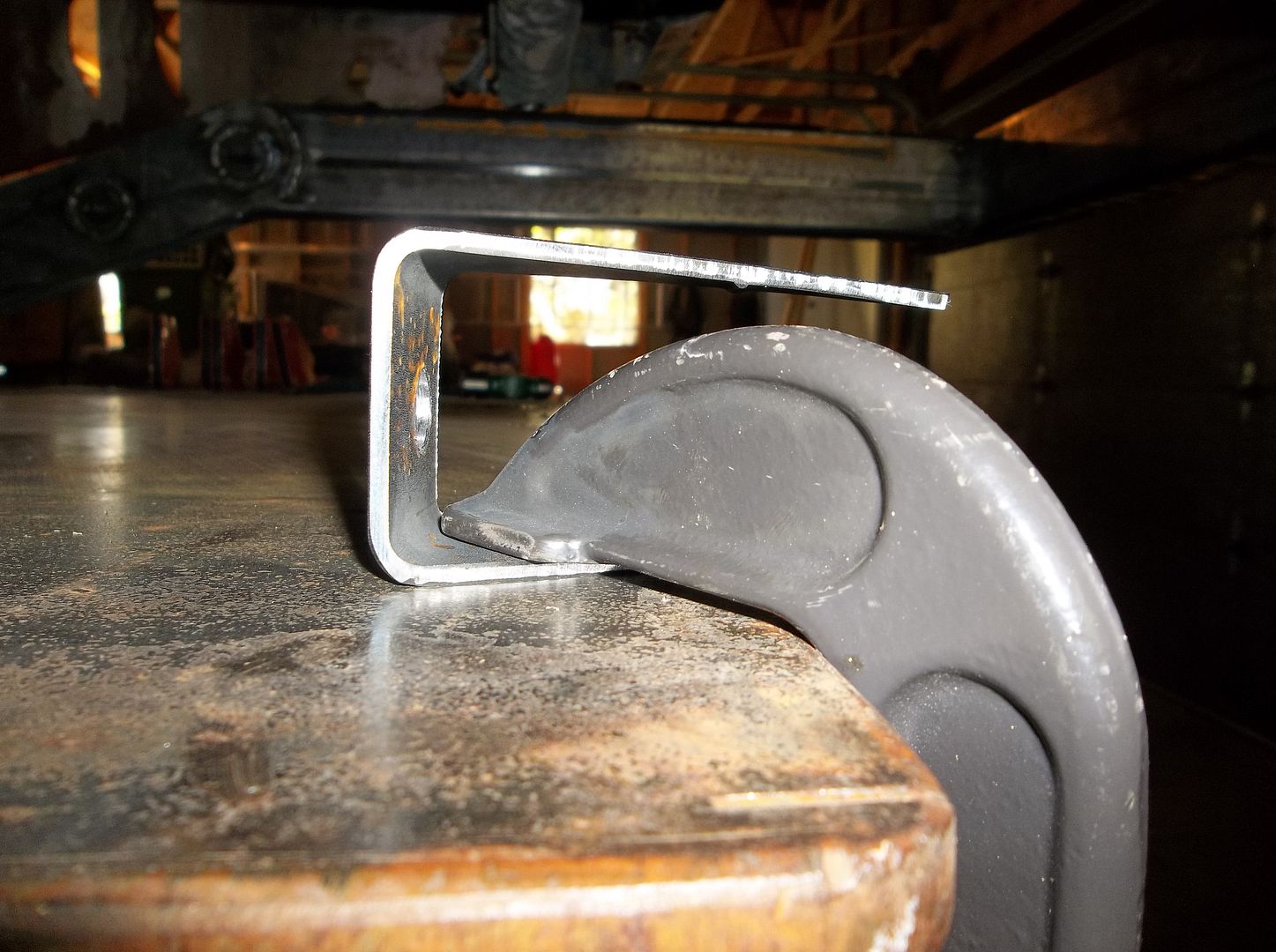
The downside to doing it this way is that welding tubing usually does this when you cut it apart.....
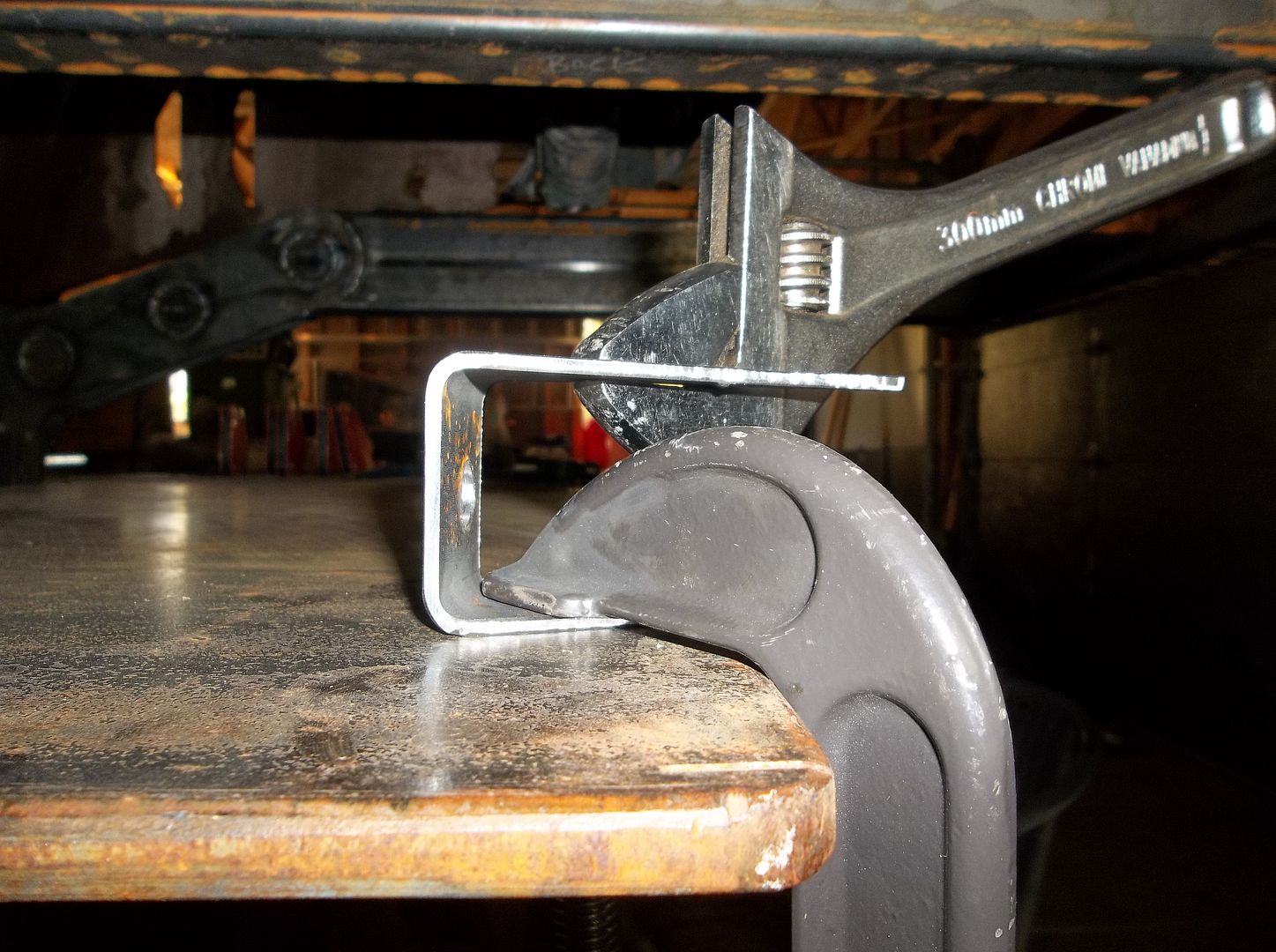
Ater a little love with a large crescent wrench you can get it straight enough though.
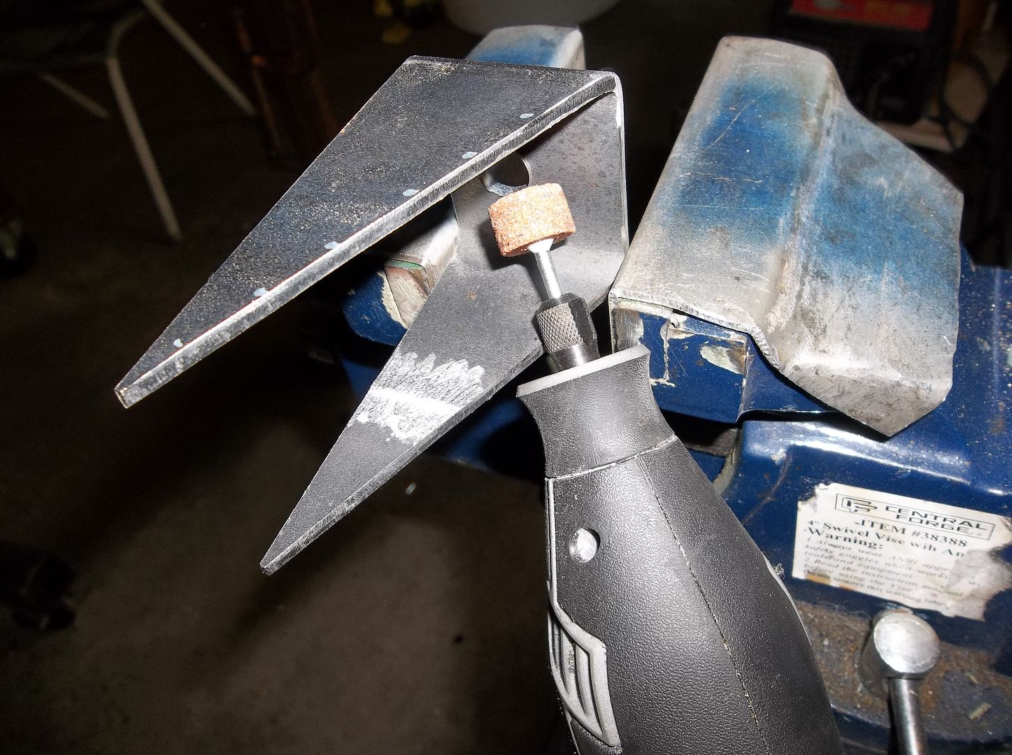
Then you can clean out the weld seam in the tubing if you want so it looks a little cleaner in the end.
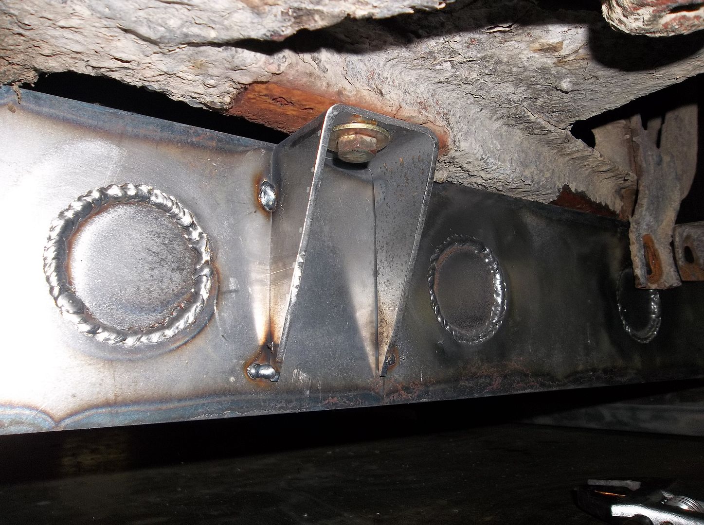
Now at this point you realize when you where cutting the two mounts apart on the saw you cut the diagonal the wrong way!! Well, at least I didn't have to stop for pictures on the next set. They only take about 15 minutes to make a pair.....

Next I drill out whatever holes I can while the part is whole on my monster expensive fancy drill press. I always try and drill in steps. These holes where going to be 1/2" in the end so I started with a 1/4" hole as a pilot after center punching the location.

The part is then cut to length on the saw. Note: these little saws, all joke aside, are SUPER handy to have around for the garage fabricator!

This is what you end up with. That doesn't look like much of a body mount, and wait, you drilled TWO holes in it. That just looks stupid.....

After a 30 second or less saw conversion I cut the mount into two parts. OHHHHHHH....it's two mounts

The downside to doing it this way is that welding tubing usually does this when you cut it apart.....

Ater a little love with a large crescent wrench you can get it straight enough though.

Then you can clean out the weld seam in the tubing if you want so it looks a little cleaner in the end.

Now at this point you realize when you where cutting the two mounts apart on the saw you cut the diagonal the wrong way!! Well, at least I didn't have to stop for pictures on the next set. They only take about 15 minutes to make a pair.....
Metcalf
Expedition Leader
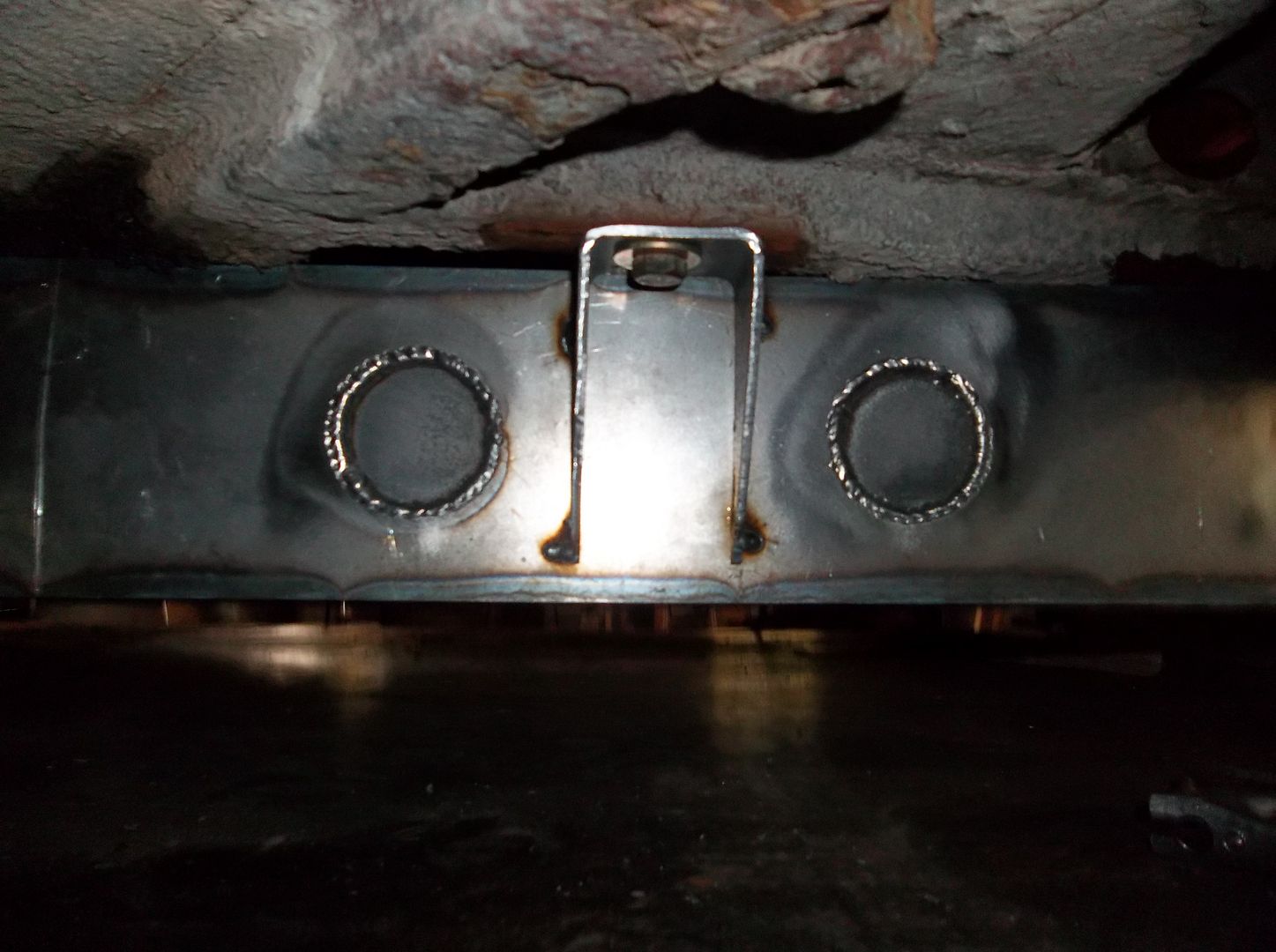
They turned out pretty straight. I'm not going to fully weld them till I take the body off at some point....
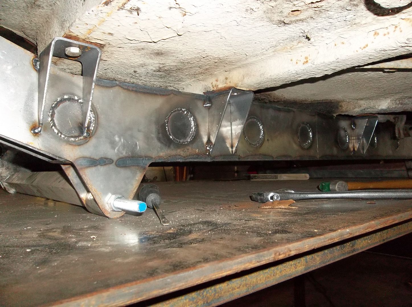
After the first two I made another set for the passenger side of the frame on the outside. These where pretty easy to get to. These where a pair and both offset the same amount. They where 1.375" offset from the side of the frame and a 1/2" mounting hole seemed to work the best for getting alignment. I didn't mess up on this pair the first round.
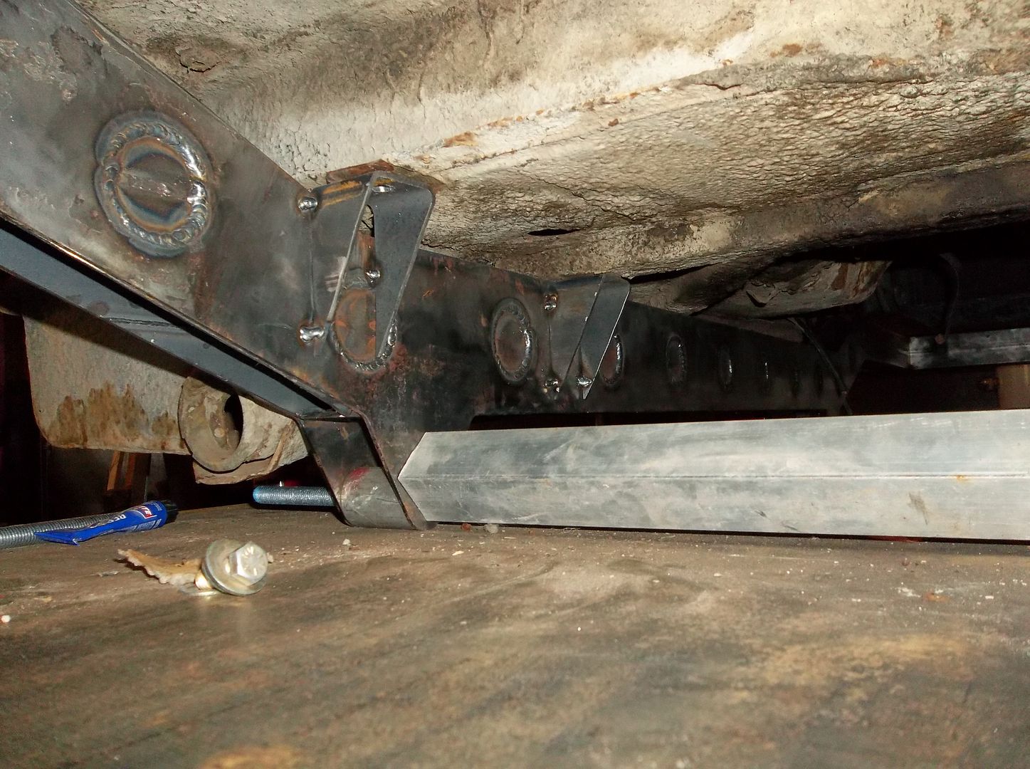
These two on the MB frame are a total pain in the rear. They where built at 1.125" offset with a 1/2" hole. There rear mount was pretty easy since you can get at the mounting bolt. The forward mount has a captured 3/8-16 nut in the hat channel. This one was a total pain to get tack welded!
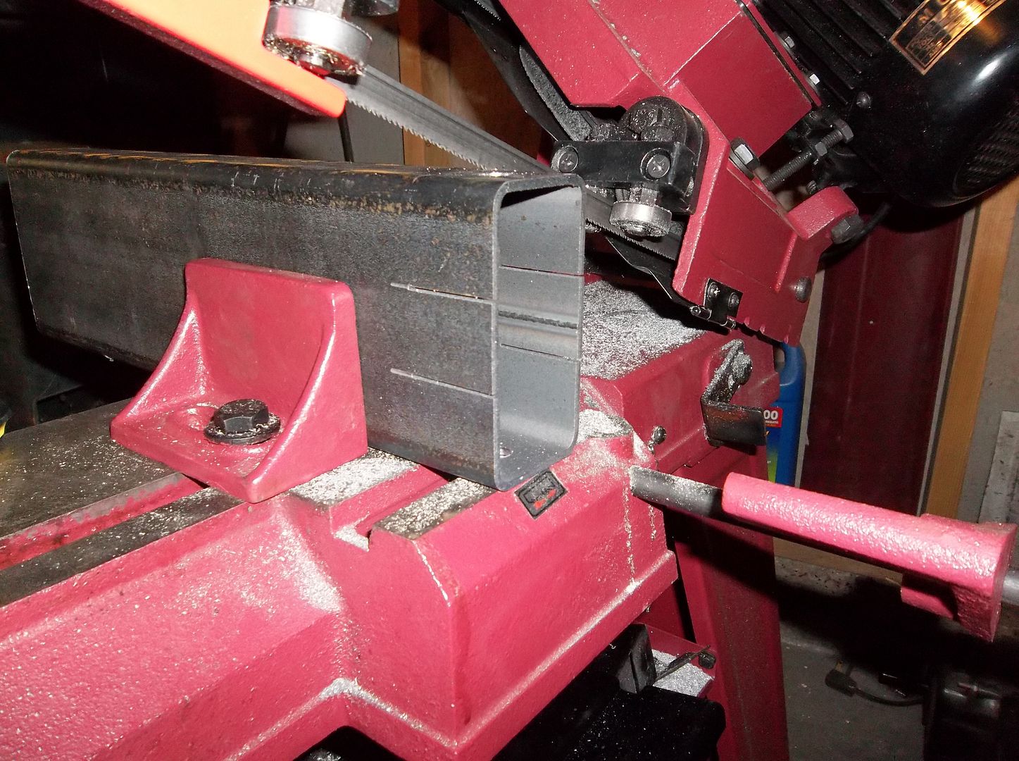
What the????? ( saw trick )
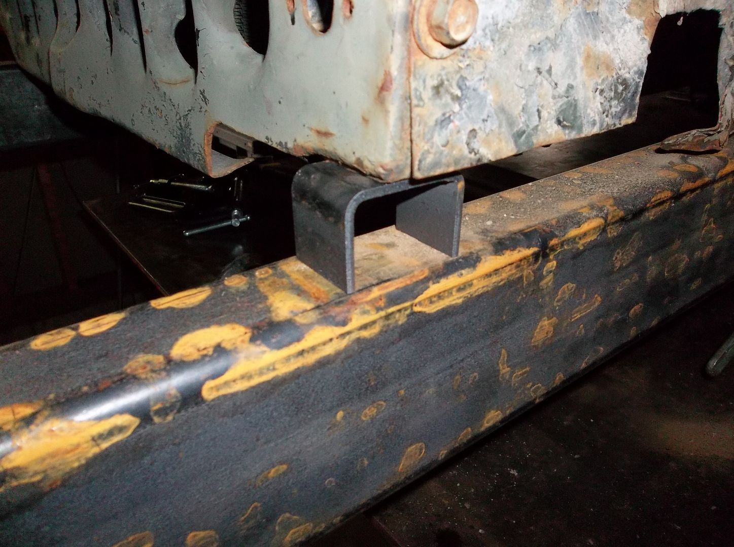
OOOOHHHHHHHH..... Two simple grill mounts for the price of one.
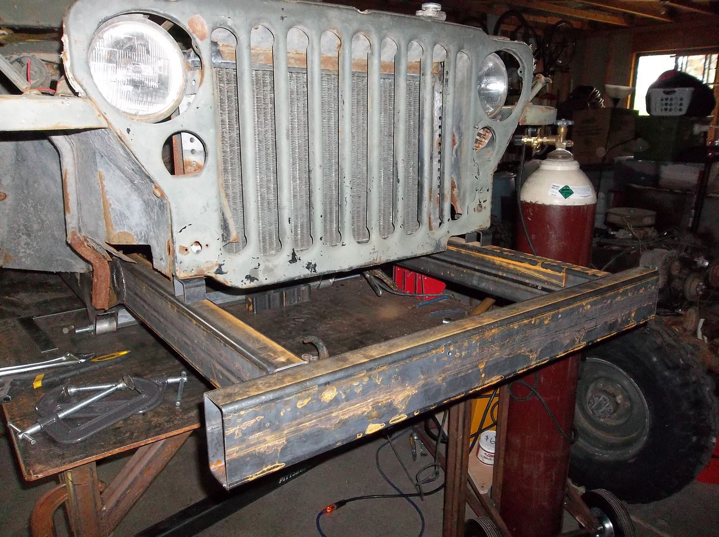
Boy that front frame section looks LLLLOOOOONNNNGGGG! with the longer springs and the wheelbase pushed 3" forward it get a little longer. The grill is getting pushed forward a bit with the fender work and there is a nice big upright winch to fill in the rest......and a steering box too. Maybe its not too bad, or maybe the wide angle lens makes it look longer than it is?
jeepdreamer
Expedition Leader
Coolness at work! Good job! If i may add a little to your side bar about the usefullness of the band saw? I can see where a quality one of these would be very handy. I would like to specify "quality" as the el cheapo one I bought from Harbor freight was a real lemon. Granted I bought the smaller of the two they offer but it was pathetic! But it did produce crooked cuts consistantly...everytime! :[ That is when the band didn't jump the wheels and make me stop to fix it. I ended up literally throwing it away.. and I hate doing that!
Keep the progress rolling... I'm anxious for a ride!
Keep the progress rolling... I'm anxious for a ride!
Metcalf
Expedition Leader
HAHA! My saw is the HF cheapy. I got it for $225 delivered to my door. I spent a few days setting it up and tuning it. It was WAY off from the factory for sure. Once you get the blade tension, spring tension, and blade alignment done they really seem to get MUCH better. Add in a $15 american made replacement blade an they are just wonderful. They are not a set up and go kinda thing though. You really have to tune the machine in....or at least I did. I have cut a LOT of stuff on this litte guy so far. I'm not saying it would work for a full blown fab shop, but for the average garage hack like me it works GREAT!
Where did you throw it away at?
Where did you throw it away at?
D
Deleted member 9101
Guest
Awesome work man!!!!
reece146
Automotive Artist
Boy that front frame section looks LLLLOOOOONNNNGGGG! with the longer springs and the wheelbase pushed 3" forward it get a little longer. The grill is getting pushed forward a bit with the fender work and there is a nice big upright winch to fill in the rest......and a steering box too. Maybe its not too bad, or maybe the wide angle lens makes it look longer than it is?
Once you get it all filled in with "stuff" it will look fine. The key from an aesthetics point of view is to place the front axle in such a way that the area is "crowded" by the front tires to make the eye not focus on that area.
Seen "rat rod" type Jeeps and T's done that way and it makes a difference to focus the eyes. Just place the axle as far forward as possible and still get good steering linkage geometry.
I guess you are retaining front leaves so your options may be limited. Using a SOA specific leaf with an offset centre pin might help a bit. Toyota mini-trucks with SFA and XJ rear leaves are offset. Of course the full size stuff like F[2,3]50s and older Chevs but you may not have the room for something that long in the front?
Metcalf
Expedition Leader
Once you get it all filled in with "stuff" it will look fine. The key from an aesthetics point of view is to place the front axle in such a way that the area is "crowded" by the front tires to make the eye not focus on that area.
Seen "rat rod" type Jeeps and T's done that way and it makes a difference to focus the eyes. Just place the axle as far forward as possible and still get good steering linkage geometry.
I guess you are retaining front leaves so your options may be limited. Using a SOA specific leaf with an offset centre pin might help a bit. Toyota mini-trucks with SFA and XJ rear leaves are offset. Of course the full size stuff like F[2,3]50s and older Chevs but you may not have the room for something that long in the front?
Thanks for the ideas. The front frame looks long, but its not THAT bad compared to stock. Stock is 10.5" from the grill to the end of the factory bumper. My frame is currently 14" from the frame to the grill to the front face of the bumper. The grill will be going forward about 1.5" with the fender 'highline' rework. That makes the front at about 12.5" from the grill to the end of the bumper. I have a 2" thick bumper, so that leaves a cavity about 10.5" deep between the bumper and the grill. The winch mount will probably be 1/4" thick....then we are down to 10.25" of space. The Belleview winch is approx 9" deep, so that only leaves 1.25" behind the winch to the grill. I think that will fill the front area just fine
The front suspension is going to be 'rear' flat fender springs. Simple and easy. The frame mounts where designed around these springs for my final wheelbase. Its just a very simple suspension. They are going to be kept SUA and I will probably be running the 1" 'lift' versions.
The front axle is going forward 3" from its stock location if all my math is right.
jeepdreamer
Expedition Leader
Its Harbor Freight...! LOL! Funny, mine was green, not red? I wonder if they source them from different manufacturers? I think yours is the next bigger one from the POS I had.. mine felt like it was made out of sheet metal. And if I had half the stuff I've thrown away over the years I'd be a permenent fixture on "Horders"! LOL!
As a side question... how hard would it be for you to re-produce this frame? Any idea in weight diff. between it and the factory one? Have a guess on how much $$ your into it for so far??
As a side question... how hard would it be for you to re-produce this frame? Any idea in weight diff. between it and the factory one? Have a guess on how much $$ your into it for so far??
Metcalf
Expedition Leader
As a side question... how hard would it be for you to re-produce this frame? Any idea in weight diff. between it and the factory one? Have a guess on how much $$ your into it for so far??
It would be fairly easy to reproduce, that's the whole idea:sombrero:
I plan on putting up a file containing the information needed to have the side plate cut and an overall print of the frame for construction. The plan from the beginning was to make a flat fender frame simple and affordable for people. I think charging $2000 for a frame is ridiculous personally. While I can see the value in building one, that kind of cost is a bit much.
I am waiting to release the information until I get mine built all the way. Then I can transfer the body mount locations over to the prints. I would recommend building the mounts with the body since these flat fender bodies can be a little 'off' after 70 years.
I think it was under $200 for the laser cut side plates and about $140 for two sticks of 2x4x1/8 tubing ( with my work discount ). So far. I have basically used only the 2x4 tubing for construction. I had a few little scraps of material out of the bin for the rear inner body mounts, but those could be simplified I think.
Ideally. All the rectangular tubing could be cut on a laser tube cutter ( not as expensive as it sounds ) and then the frame could be basically self jigging if it was done right. You could basically have a pre-cut frame in a box type package. I think that would be really cool. Even the body mounts could be pre-cut out of the same tubing. The body mounts could then be 'tab and slot' into the side plates so the location would be known. The same 'tab and slot' could be carried over to all the crossmembers also.
This frame is pretty specific for the Willys MB tub. With enough time and experimentation I am sure the came design could be carried over to cj2a, cj3a, or for that matter any of the straight rail vehicles up to the early cj5s.
Weight difference. I don't know yet. The new frame is still under 200lbs I believe. I will have to see what the old frame is when I get it all stripped down.
The other thing to think about is that the frame I designed is a bit of a modified version. The wheelbase as been tweaked and the springs changed to the longer rear springs in front. I don't know how many people are going to want something like that, but I did
Similar threads
- Replies
- 7
- Views
- 834
- Replies
- 4
- Views
- 2K
- Replies
- 65
- Views
- 6K

