You are using an out of date browser. It may not display this or other websites correctly.
You should upgrade or use an alternative browser.
You should upgrade or use an alternative browser.
Unicorn on the Ocean - 1120AF Coming to Canada
- Thread starter whomisi
- Start date
whomisi
Active member
I'm going for rail on rail for highway manners and robustness for the chassis. I've got a variety of die springs so I can tune the hold down tension and preload along the length. As well as limit the travel if required. Starting point is 6" of travel at the front.That is some real progress there, must be nice to have it done! Have you decided on how and where to pivot the subframe on the truck frame?
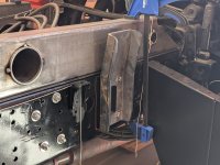
You can see the hold downs below, just a bolt in the image as I was setting it up for welding.
I had to drill out the chassis hold down rivits and replace them with countersunk bolts for clearance to the springs. The springs are 30mm OD.
There's 1/4" rubber between rail and chassis to keep the noise down.
I know this still leaves some torsion in the box, but on balance it's a better fit for how the truck will be used, and simplicity.

whomisi
Active member
Sort of, bolted to the frame but same idea. Taller than the maximum travel, adjustable height to set them snug to the frame. And with a UMHW slippery plastic plate to save the paint. 5/16 steel, formed and welded, silly strong.Are you welding some 'angled tabs' in to guide the frame back into the right position when they meet up again?
whomisi
Active member
And for completeness, this is the bracket I designed for holding the rear of the subframe to the chassis. This connects close to some diagonal braces that connect to the rear cross member. The factory cross member is welded to the chassis as well.
This is part of the winch extra structure so it should tie everything together nicely.
Four 5/8 bolts per side, grade 8, torqued FT.
I didn't put it right at the very back as I didn't want the box flopping around too much, it's halfway between the rear and the rear spring hangers. Tough balancing act for highway manners, off road articulation, and limiting box torsion.

GR8ADV
Explorer
Great stuff. I could never do this.
Curious, and maybe I missed it. By extending the frame rail from 3.65 to 4.2, the bending stresses (roughly speaking) in the beam rail increase by about 30-35% +\~ over what it was designed for. Did you have to strengthen the frame rail itself to account for this. Or is it covered elsewhere.
If you have addressed this and I missed it I apologize.
I (we all) really appreciate you taking the time to post all of this
Last edited:
whomisi
Active member
Good question. Mercedes provides a guide, which can be found on their website through the "Builders Portal", on how to extend/shorten the chassis and that includes adding reinforcing profiles inside the frame.Curious, and maybe I missed it. By extending the frame rail from 3.65 to 4.2, the bending stresses (roughly speaking) in the beam rail increase by about 30-35% +\~ over what it was designed for. Did you have to strengthen the frame rail itself to account for this. Or is it covered elsewhere.
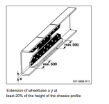
It also gives pointers like if you extend beyond the longest standard wheelbase, then increase strength. These screenshots are from the guide which I translated.

There are also requirements for cross member spacing, as well as maximum length that one section of driveshaft can be before a centre bearing multi part driveshaft has to be used.
On top of this (literally) is the subframe, which spreads the load along the length of the frame reducing the bending forces on the extended section of chassis. For reference, I have used subframe box sections that are 3x6x0.188 in approximately the same grade of steel as the chassis, which is stronger than your regular mild steel. The cross member and the reinforcing parts are also this same steel, laser cut and formed from 1/4 plate.
This reminds me why it's taken two years from buying the truck to getting back to a driving chassis cab.... now I don't feel so bad about the slow progress!
whomisi
Active member
Time for the cliché photos of the "subframe test", which is no way an actual test since there is no load on anything. Anyway, it looks cool so I'm posting it.
It's also occurred to me that the stiffness of the box will far exceed any kind of steel subframe. So in real life, I feel like the box in unavoidably going to take all torsion that goes into the frame and making a stiff frame will make little difference to that fact. Either way I'm happy with how mine has turned out.
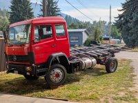
The springs are in place and I'll give those a test next time I have the truck outside. Photos below are at 5" of separation. I was going to shoot for 6", but this feels like enough plus then I can put more preload on the springs to stop them rattling around.


whomisi
Active member
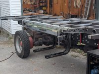
Small update but a big amount of work. I built a slide out mini deck for the stairs to hide under. I don't want the style of stairs that stick straight out but instead the steps will run along side the truck towards the back wheel. They will deploy from under this deck.
Using unistrut and some of the old service body on the back I fabri-cobbled this together. Looks simple, but remarkably hard to get flat and square. But it works a treat and it's really nice and stiff so it doesn't feel like it's going to break. I also have a sensor on one of the two locking pins so that if it isn't locked properly, and the engine starts, it will sound an alarm in the cab.
Deck surface is just a temporary solution until I find some nice looking composite deck boards.


whomisi
Active member
The panels arrived! It's a 5500x2400x2160ish Total Composites box. I'm grateful that Andreas was willing to supply a DIY kit, I always had that in mind and spoke with him before they moved away from DIY kits. It's been a great experience so far.
The size of the panels meant they turned up on a rack, which took two forklifts to unload. Then trailered to my shop where a crane truck lifted it off and slotted it into place. Apparently I know just the right people!!
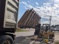


This left me VERY short on space, so the next step was to put some vertical bars on the flip side of the rack, then stand the panels up and remove half the racking. I've now got space to work again, a stack of steel box section, and the panels are in close to the right order. The floor being right where I need it.
I stood these on their end one at a time by hand, by myself. Amazing how light yet stiff these panels are. It's nice to finally get a true idea of what the box will eventually feel like. The floor panel is quite a lump, lots of cross members.
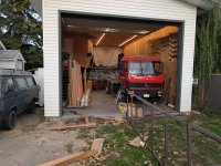
The size of the panels meant they turned up on a rack, which took two forklifts to unload. Then trailered to my shop where a crane truck lifted it off and slotted it into place. Apparently I know just the right people!!


This left me VERY short on space, so the next step was to put some vertical bars on the flip side of the rack, then stand the panels up and remove half the racking. I've now got space to work again, a stack of steel box section, and the panels are in close to the right order. The floor being right where I need it.
I stood these on their end one at a time by hand, by myself. Amazing how light yet stiff these panels are. It's nice to finally get a true idea of what the box will eventually feel like. The floor panel is quite a lump, lots of cross members.

whomisi
Active member
Another month goes by!
The truck has been back on the road for the first proper run since it was sliced in half. Seemed to drive nicely enough, although some heavy vibrations at one specific speed. I suspect that's due to being completely unloaded. Will keep an eye on that.
I took it to sandblast the subframe, that was an unpleasant few hours. For anyone that's seen the process, you'll understand. Suited up with positive air pressure helmet. Loud, dusty, half blind. And I did a pallet of other bits and bobs at the same time.
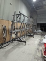

Then I left it behind and it was all powder coated with two coats of zinc infused powder. A week later I was back to re attach and collect the parts.
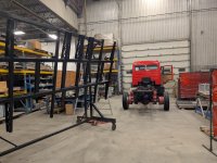
I also had a friend weld up the grey water tank. It's the original fuel tank and is stainless steel. I cut it shorter and added some bungs. Should do just fine for grey water. I guess we'll see.

I also weighed the truck on the way to unload the subframe. 3500kg on the front axle, 2300kg on the rear. That's with subframe, one fuel tank half filled. Leaving me about 4000kg to my estimated final weight. But I've got 6000kg till gvw. Would like to keep it as light as I can of course.
Speaking of weight, I need to figure out what type of material to build cabinets with. Any suggestions?
Few more bits to bolt back onto the frame then it's time to start assembling the panels! Finally.
The truck has been back on the road for the first proper run since it was sliced in half. Seemed to drive nicely enough, although some heavy vibrations at one specific speed. I suspect that's due to being completely unloaded. Will keep an eye on that.
I took it to sandblast the subframe, that was an unpleasant few hours. For anyone that's seen the process, you'll understand. Suited up with positive air pressure helmet. Loud, dusty, half blind. And I did a pallet of other bits and bobs at the same time.


Then I left it behind and it was all powder coated with two coats of zinc infused powder. A week later I was back to re attach and collect the parts.

I also had a friend weld up the grey water tank. It's the original fuel tank and is stainless steel. I cut it shorter and added some bungs. Should do just fine for grey water. I guess we'll see.

I also weighed the truck on the way to unload the subframe. 3500kg on the front axle, 2300kg on the rear. That's with subframe, one fuel tank half filled. Leaving me about 4000kg to my estimated final weight. But I've got 6000kg till gvw. Would like to keep it as light as I can of course.
Speaking of weight, I need to figure out what type of material to build cabinets with. Any suggestions?
Few more bits to bolt back onto the frame then it's time to start assembling the panels! Finally.
whomisi
Active member
Plodding along.
With the subframe painted, and bolted back down, it was time to get the box coming together. I summoned up as many friends as I could and we wrestled the floor panel into place. The way it was stacked on the rack, which I cut away, we just had to lower it down onto the side of the subframe (where I attached a rail of soft wood) and then slide it up into place. We didn't actually have to lift it outright.
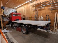
I was worried I hadn't extended the wheelbase enough, but now seeing it coming together I am happy with the proportions. It's working out well.
My subframe has an excessive number of mounting locations to the floor panel, but I wanted to tie everything together properly as the storage boxes will hang off the subframe, so the subframe needed attaching properly to the floor panel since it's stiffer. It took a long day and a half to mark, drill, tap all 44 bolts (3/8 flanged). I set them up with loctite and a little butyl to seal the hole in a simple way. The holes were 12.3mm and the bolts 9.5, I didn't have much room to mess around. I turned a small transfer/centre punch tool that could get where I needed it to get and it worked out perfectly. Every bolt went right in.

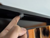
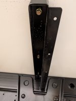
I have started cutting the corner profiles ready to glue the panels together. I wanted to fully seal the foam, even inside the corner caps. The plan is that this way I can leave the corner caps off for a while, run wires for my marker lights, outside camper lighting, backup camera, anything else I want access to the channels. And the panels themselves will be fully sealed. If ever water gets behind any of the lights etc, it won't have any access to the panels themselves.
However this does make my life a little harder right now, but it's not too bad since everything will be buried under the corner caps anyway. It's certainly easier since I have everything modelled in CAD, I can just copy dimensions after doing the test fitting in the virtual world.


Comments and criticism welcome, everyone's being very quiet around here lately.
With the subframe painted, and bolted back down, it was time to get the box coming together. I summoned up as many friends as I could and we wrestled the floor panel into place. The way it was stacked on the rack, which I cut away, we just had to lower it down onto the side of the subframe (where I attached a rail of soft wood) and then slide it up into place. We didn't actually have to lift it outright.

I was worried I hadn't extended the wheelbase enough, but now seeing it coming together I am happy with the proportions. It's working out well.
My subframe has an excessive number of mounting locations to the floor panel, but I wanted to tie everything together properly as the storage boxes will hang off the subframe, so the subframe needed attaching properly to the floor panel since it's stiffer. It took a long day and a half to mark, drill, tap all 44 bolts (3/8 flanged). I set them up with loctite and a little butyl to seal the hole in a simple way. The holes were 12.3mm and the bolts 9.5, I didn't have much room to mess around. I turned a small transfer/centre punch tool that could get where I needed it to get and it worked out perfectly. Every bolt went right in.


I have started cutting the corner profiles ready to glue the panels together. I wanted to fully seal the foam, even inside the corner caps. The plan is that this way I can leave the corner caps off for a while, run wires for my marker lights, outside camper lighting, backup camera, anything else I want access to the channels. And the panels themselves will be fully sealed. If ever water gets behind any of the lights etc, it won't have any access to the panels themselves.
However this does make my life a little harder right now, but it's not too bad since everything will be buried under the corner caps anyway. It's certainly easier since I have everything modelled in CAD, I can just copy dimensions after doing the test fitting in the virtual world.


Comments and criticism welcome, everyone's being very quiet around here lately.
Similar threads
- Replies
- 6
- Views
- 984
- Replies
- 5
- Views
- 2K
- Replies
- 2
- Views
- 2K
