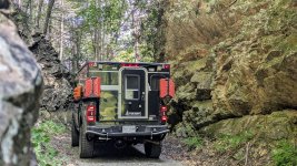
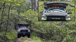
2021 RAM 3500 Tradesman | AEV Prospector | FWC Grandby

ramblinChet

Well-known member
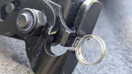
My primary goal in designing my on-board air system was to create a fast and reliable solution for inflating tires to appropriate pressures when transitioning from off-road to on-road. The difference between a 10-15 minute inflation time and the more common 20-30 minutes is significant, especially when trails demand multiple transitions in a single day. To optimize this process, I mounted Milton HIGHFLOWPRO V-style brass couplers on both sides of my vehicle, between the cab and camper, allowing me to connect to the driver’s side, inflate both tires, then repeat on the passenger side. I sourced 3.5x3.5x3.5-inch aluminum brackets and secured them to the base of my aluminum RotopaX carriers.
RC 25-295.jpg

To centralize the air system accessories, I mounted a Milton Safety Blow Gun with a 10-inch extension on the rear wall of my camper, adjacent to the air system. I used three spring clip holders for mounting, and it remains to be seen whether these clips will securely retain the blow gun on rough trails.
RC 25-296.jpg

The next phase involved transferring pressurized air from inside the camper to the external brass couplers. I applied masking tape to mark measurements, transferring precise data to ensure accuracy. My objective was to drill a 24mm hole through the aluminum base of the air compressor mount and a horizontal camper surface while avoiding a 3/4-inch-thick blind vertical wall. The hole needed to be close to the wall without contacting it. Through meticulous, repeated measurements, I achieved satisfactory results. A high-temperature silicone rubber grommet was installed in the hole to protect the air line, as shown in the accompanying image.
RC 25-297.jpg

While inspecting the engine compartment, I noted significant dirt accumulation, prompting a thorough cleaning before my next trip. I installed a Victron Energy MEGA Fuse Holder to power a Victron Energy Orion XS 50-amp DC-DC charger, which charges my house batteries while driving. Based on my calculations, Ancor 4 AWG wire was suitable for this application. The RAM's High Amperage Power Point (HAPP), an M8 stud on the battery rated for 300 amps, facilitates this connection, located on the driver’s side within the power bus.
RC 25-298.jpg

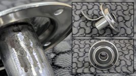
Recently, I noticed a soft grinding noise from the front of my truck at 15-25 mph, louder during left turns and quieter during right turns. Despite my hearing challenges from past exposure to helicopters and machine guns, and my habit of driving with windows down and radio on, I suspected the passenger-side hub assembly (wheel bearing) was failing. After driving briefly and stopping in a parking lot, I confirmed the passenger-side hub was significantly hotter than the driver’s side. On a 95°F day, the driver’s side was hot (approximately 110°F, touchable for 5-10 seconds), while the passenger side was very hot (approximately 120°F, touchable for 1-3 seconds). Using a Fluke 87V-MAX multimeter and Type-K thermocouple, I measured the temperatures, confirming the passenger-side hub assembly failure.
RC 25-299.jpg

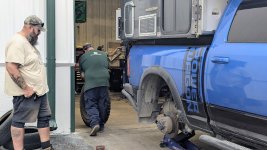
With my time in Virginia nearing an end and a strong desire to return west, I enlisted my son’s expertise to replace the faulty hub assembly. After jacking up the truck, we confirmed significant play in the passenger-side wheel by shaking it at the 3 and 9 o’clock and 6 and 12 o’clock positions, compared to the driver’s side. Within an hour, the repair was complete, and I drove away satisfied, grateful for my son’s skillful assistance.
RC 25-300.jpg

Approaching 100,000 miles on my AEV Prospector, I am planning long-term preventative maintenance, including replacing transmission and transfer case fluid, flushing engine coolant, and checking brake fluid. Using test strips from Phoenix Systems, I measured copper contamination in the brake fluid at 30-100 ppm, indicating no immediate need for a flush. Additionally, I plan to test the brake fluid’s moisture content, as brake fluid is hygroscopic, and increased moisture lowers the boiling point, reducing braking performance and causing corrosion. In my superbike racing days, I flushed brake systems between races to ensure optimal performance.
RC 25-301.jpg

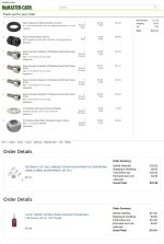
For historical purposes, I have documented the expenses associated with this work.
RC 25-302.jpg

The AEV Prospector’s steering knuckle, drag link, and track bar, part of AEV’s High Steer Kit, are custom-engineered components that address longstanding aftermarket suspension challenges. Few companies possess the engineering expertise, OEM connections, and resources to develop such solutions.
RC 25-303.jpg

If you are interested in a technical discussion related to What It Really Takes to Build a Factory Overlander with Dave Harriton from AEV - here is a great podcast:
 
Last edited:

ramblinChet

Well-known member
This phase of the project focuses on removing the Four Wheel Camper from my truck bed and fabricating custom-length air lines for my Overland Air Device 145 PSI (OAD-145P). To prepare for camper removal, I first detached two RotopaX 2-gallon water containers from the camper’s front and two 20L Wehrmacht-Einheitskanister (Armed Forces Standard Canisters) from the rear. Next, I installed four Rieco-Titan mechanical camper jacks at each corner of the camper. While some pop-up camper owners keep jacks permanently installed, I remove mine to avoid potential damage from obstacles on rugged trails, which could compromise the camper’s aluminum structure.
RC 25-304.jpg

When pricing camper jacks, I was surprised to find that a set of four new Rieco-Titan jacks cost just over $1,000, with used units ranging from $700 to $900. I briefly considered designing and building my own jacks but ultimately decided against it. Upon inspecting the Rieco-Titan units, their quality was evident, reflecting decades of engineering refinement. Each jack weighs approximately 25–30 pounds, features smooth and robust internal gearing, and can support up to 2,000 pounds independently. The jacks include manual handles, but I also purchased a $29 drill adapter, which significantly improved efficiency.
RC 25-305.jpg

Time constraints forced a change in my approach to removing the factory-installed turnbuckles. Initially, I planned to soak them with penetrating oil and use a wrench, but the threaded sections were too rusted. Instead, I used a 4.5-inch angle grinder with a cutting wheel, severing all mechanical connections between the camper and truck in under five minutes. I raised the camper by first elevating the front 2–3 inches, then the rear, using a small level to maintain pitch and roll within acceptable limits. Once the camper cleared the truck bed, I moved the truck forward a few feet, disconnected the electrical harness, and drove out from under the camper. Clearance was tight, with approximately 0.50–0.75 inches between the fender flares, wheels, and camper jacks.
RC 25-306.jpg

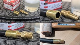
My initial design of the OAD-145P incorporated DOT-approved push-to-connect fittings and SAE J844 tubing, commonly used in heavy-duty trucks. This choice was driven by the availability of replacement components at truck stops. However, after further research and discussions with full-time overlanders, I determined that while cost-effective and easy to assemble, this system lacked long-term durability. I shifted to custom-length air hoses using Continental 3/8-inch rubber air hose and Milton HIGHFLOWPRO brass fittings. Selecting compatible components was challenging, as the outer diameter (OD) of hoses with identical inner diameters (ID) varies significantly. The goal was to choose a brass ferrule that slides over the hose snugly enough to stay in place but loosely enough to allow full insertion of the brass end fitting. Research suggested using soapy water to ease assembly, noting that overly easy insertion could lead to leaks. Even with soapy water and significant force, I could only seat the brass end fitting halfway; a rawhide hammer and several firm strikes fully seated the fittings.
RC 25-307.jpg

The final step involved selecting the appropriate hardened steel ribbed die for the Heavy-Duty Hose Crimper Tool to crimp the ferrule. This tool accommodates hoses from 1/4-inch single-braid to 3/8-inch two-braid, with die bore sizes of 0.484", 0.531", 0.578", 0.625", and 0.687". While not ideal for all builds, this solution met my need for durable, custom-length hoses capable of withstanding diverse conditions. It will be interesting to evaluate their longevity in real-world use.
RC 25-308.jpg

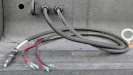
The first hose I fabricated delivers air from the OAD-145P inside the camper, through a horizontal surface, to the exterior for distribution. I incorporated a loop in this line to prevent kinking, extend service life, and reduce stress on the fittings.
RC 25-309.jpg

With the camper off the truck, accessing its exterior was straightforward, allowing me to preconfigure fittings and measure air lines accurately. Masking tape was invaluable for marking and noting measurements on the camper’s flat aluminum surface. For reference, a 1/4-inch NPT (National Pipe Taper) threaded fitting has 18 threads per inch (TPI), so each full turn shortens the assembly by 0.0556 inches along the axis. Initial hand-tightening requires approximately 3–4 turns, with final wrench-tightening adding 1.5–3 turns, resulting in a total axial shortening of 0.25–0.39 inches. This data informed precise hose length calculations before cutting.
RC 25-310.jpg

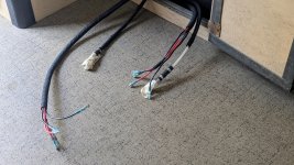
The final assembly uses Continental hoses with Parker-Hannifin elbows and tees, Milton ferrules, and HIGHFLOWPRO couplings and end links. Each hose includes a calculated amount of slack to accommodate camper flex during off-road use. Designing and building the OAD-145P was rewarding, and I anticipate reliable performance on the trail. The air line transitioning from inside to outside the camper (visible in the inset image) may require sealant to ensure a weather-tight interface.
RC 25-311.jpg

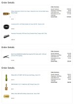
For this phase, I documented expenses carefully. I initially considered purchasing the hose crimper from Milton, priced at $276, but opted for a comparable unit that saved over $150. The Klein Tools cutter performed flawlessly, producing clean, perpendicular cuts on the double-braided hose.
RC 25-312.jpg

Without the camper, my AEV Prospector feels significantly different in both appearance and handling. If I could, I'd trade it all for an automator...
RC 25-313.jpg
 
Last edited:

ramblinChet

Well-known member
You didn't replace both front hub bearings?

Negative - the drivers side was tested and is fine right now. There is always a chance it may last another 50k miles although I am prepared to replace it as soon as it begins to degrade.
 

ramblinChet

Well-known member
The Overland Air Device 145 PSI (OAD-145P) is operational and performing within specifications. Initially pressurized to 145 PSI, the system stabilized at 135 PSI within minutes. This pressure drop is attributed to thermal equilibrium, hose and line expansion, and minor leaks or settling. As compressed air cools to ambient temperature in the aluminum tank and lines, its pressure decreases. Hose and line expansion results from slight stretching under initial pressurization. Minor leaks at fittings or valves are typical in new systems as they stabilize. A pressure loss exceeding 10 PSI per hour in a mature system warrants further investigation. The VictronConnect app, displaying the BMV-712 Battery Monitor, confirms that the 12-volt ExtremeAire Magnum compressor drew a maximum of 82.9 amps and pressurized the system in under 30 seconds, aligning with predictions and establishing a baseline for future measurements.
RC 25-315.jpg

Electrical connections between the truck and camper are located on the driver’s-side forward wall of the truck bed. The Marnico 70A Trolling Motor Receptacle and Plug, specified four years ago, continues to perform reliably. For 50A DC-DC power transfer between alternators and house batteries, 4 AWG wire connects to a Blue Sea Systems Feed-Through Connector (red). The chassis ground uses 1/0 AWG wire to connect system bus bars to the vehicle frame. Drilled holes for these connections are coated with protective paint for corrosion resistance.
RC 25-316.jpg

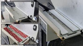
When mounting the 3.5-inch aluminum bracket to the bottom of the aluminum RotopaX carriers, rounded-head screws were initially used. To prevent potential damage to full RotopaX containers from focused pressure, 1-inch x 1/8-inch aluminum flat stock strips, bonded with 3M VHB tape, were installed as a temporary solution. Countersunk flat-head screws are planned for a future upgrade to provide a permanent, damage-free mounting solution.
RC 25-317.jpg

The chassis ground connection enhances electrical safety, stabilizes voltage reference, and reduces electrical noise. System designers are encouraged to implement a clean chassis ground connection to the vehicle frame. A bolt, cut to length and chamfered using a bench grinder, was used for this installation to ensure a secure and precise fit.
RC 25-318.jpg

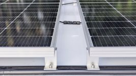
The solar SAE connector, installed on the camper roof by Four Wheel Camper during manufacturing, has performed adequately but will be upgraded to a more robust variant. Additional electrical connections, located below the rooftop connector, are concealed above the wooden lift-assist bar on the camper ceiling.
RC 25-319.jpg

Installation of four Yakima 60-inch tracks on the camper’s aluminum roof required drilling 44 blind holes into a thin, one-piece aluminum roof supported by 1-inch square aluminum tubing. This complex task required extensive research and consultation, leading to the decision to upgrade components and adopt a precise installation method. Tracks were centered, and distances to the camper’s front and rear faces were measured. Internally, wooden trim strips attached to the underside of the 1-inch tubing were located. A 1/16-inch pilot hole, centered on the strip and piercing the roof, established reference points for track alignment. Tracks were aligned parallel to the camper’s perimeter using percussion testing, temporarily taped in place, and marked with a Starrett automatic center punch. The presence of wood in the outermost beams was confirmed. Pilot holes for outermost beams were 5/64-inch (0.0781"), intermediate holes were 1/8-inch (0.1250"), and final holes were drilled with a #21 bit (0.1590") per the screw manufacturer’s specifications.
RC 25-320.jpg

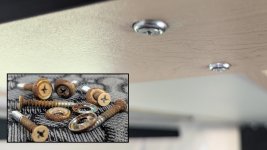
Butyl rubber sealing tape (1-1/2") was applied under the tracks, and screws were re-torqued after settling. 3M 5200 marine-grade adhesive sealant was applied to each screw. Unlike standard installations using 24 screws, all 44 holes were utilized with tri-lobular 10-32 x 3/4" Fastite sheet-metal screws, which provide enhanced thread engagement in 0.028" to 0.063" thick sheets, preventing overtightening and thread damage.
RC 25-321.jpg

The initial Yakima T-bolt screws were incompatible due to overly thick heads; a call to Yakima provided the correct anchor plates for the T-slots. A Newborn 250 caulk gun with an 18:1 thrust ratio was selected for applying the 3M 5200 marine-grade adhesive sealant after researching thrust ratio compatibility. The tri-lobular screws, T25 Torx bit, #21 drill bits, butyl rubber sealing tape, and 3M 5200 adhesive were procured earlier here and here for this installation.
RC 25-322.jpg

The Yakima tracks were finalized by trimming excess butyl rubber tape flush, ensuring a clean and secure mounting system. Drive like the wind straining the limits of machine and man, laughing out loud with fear and hope I've got a desperate plan...
RC 25-323.jpg
 
Last edited:

ramblinChet

Well-known member
Over many months, I have carefully considered the optimal routing for the exhaust from the Wallas Nordic DT diesel cooktop and heater to the exterior of the camper. As a reminder, the Wallas unit is mounted atop the MES-K470 (Modular Energy System housed in a Zarges K470 case), which is densely packed with Victron Energy components. The exhaust must pass through this enclosure before exiting the camper. While it may appear counterintuitive to route diesel exhaust through a confined space containing temperature-sensitive equipment - and indeed, this is likely why no one else has attempted such a configuration - I thrive on these challenges. With decades of experience in designing, fabricating, and commissioning projects deemed impossible by others, I proceeded confidently. Once my exhaust plans were finalized, the only missing component was a straight exhaust pipe. I contacted Chris at Scan Marine USA one final time, and he informed me they had just received straight exhausts, albeit with a curved mounting bracket welded on. This posed no issue; I carefully removed the unnecessary bracket using an angle grinder. The result may not be aesthetically perfect, but it functions reliably.
RC 25-324.jpg

The subsequent step involved drilling a 45 mm hole through the MES-K470 enclosure, sized to accommodate a high-temperature rubber bushing, a 28 mm stainless steel exhaust pipe, and surrounding exhaust insulation. Ideally, the placement of this exhaust penetration should have been determined during the initial design phase. However, at that time, the only available exhaust option from Scan Marine featured a tube bent 90 degrees relative to the mounting surface, which influenced my early decisions. After drilling, I deburred the edges and thoroughly vacuumed the interior to eliminate any contaminants.
RC 25-325.jpg

The corresponding hole through the camper wall was drilled at 32 mm. To ensure perfect concentricity between the interior 45 mm hole and the exterior 32 mm one, I first drilled a pilot hole through both surfaces. Another key challenge in penetrating the camper wall was avoiding damage to structural members, wiring, or positioning the exit in a location where exhaust fumes could reenter via a window or door. For verification, I partially disassembled the wall and inspected the corner. To my surprise, the planned location aligned precisely with a 4-inch-wide by 12-inch-tall wooden structural element - ideal for routing the exhaust. This was fortuitous, and I must emphasize that thorough research and planning for exhaust routing should have occurred months earlier. The total exhaust length exceeds one meter, with combined turns not surpassing 180 degrees, ensuring acceptable backpressure for efficient combustion, gas flow, and safety.
RC 25-326.jpg

Returning my attention to the MES-K470 and finalizing the solar system installation, I removed the new solar panels to shorten their wires and replace the inferior connectors with genuine Stäubli MC4 cable couplers.

Connectors not made by Stäubli which can be mated with Stäubli elements and in some cases are also described as ”Stäubli-compatible” do not conform to the requirements for safe electrical connection with long-term stability, and for safety reasons must not be plugged together with Stäubli elements.

RC 25-327.jpg

Employing two Stäubli MCR wrenches as part of the assembly process.
RC 25-328.jpg

A completed Stäubli female MC4 cable coupler. Though it may externally resemble a male coupler, it is the internal contact that designates it as the female variant.
RC 25-329.jpg

This step required enlarging an existing 24 mm hole to 32 mm to accommodate a Scanstrut cable gland. Despite the provided template, I verified its scale accuracy, as I have encountered issues in the past with imprecise templates leading to errors in drilling or cutting metal.
RC 25-330.jpg

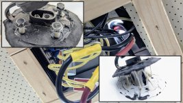
This view shows the underside from the previous image, now with the Stäubli solar wires routed in and connected to the FWC 10 AWG red and black wires. Notably, the insulation on the Stäubli 10 AWG solar wire was oversized for the Ancor 12-10 AWG butt splices, necessitating creative reinforcement with additional Ancor heat shrink tubing. I operated the solar system in this configuration for two days, monitoring connection temperatures, which remained within acceptable limits. The inset image depicts the Stäubli solar wires before splicing; my objective was to confirm polarity to ensure correct connections and prevent damage to the solar charge controller.
RC 25-331.jpg

All expenses continue to be documented for reference.
RC 25-332.jpg

Here, I am marking the solar panel frames prior to drilling four mounting holes in each of the two panels. To achieve precise hole placement at both ends of each panel, I accounted for tolerance stacking - the cumulative effect of individual dimensional variations in an assembly that can affect overall fit, function, or performance. In this instance, I drilled four sets of holes at varying widths (55.875", 55.625", 55.688", and 55.375") across a 64" span, indicating the tracks were not perfectly parallel. Extrapolating these measurements along the full 120" length of both tracks suggests each track deviates approximately 0.46875" from true center. My initial pilot holes were centered precisely on the underlying wood strips, though I acknowledge the exit points one inch higher through the roof may have been offset by up to 0.125". At the rear, my percussion testing could have introduced up to 0.250" error, so I attribute 0.280" of the 0.46875" discrepancy to my measurements, with the remainder belonging to FWC fabrication tolerances.

Here is my calculation for my portion of the error: (1) identify individual tolerances: 𝑡1=0.125 and 𝑡2=0.250 (2) square each tolerance: 𝑡1²=0.015625 and 𝑡2²=0.0625 (3) sum the squares: 0.015625+0.0625=0.078125 (4) take the square root: √0.078125≈0.280 (5) thus, my bilateral stacked tolerance is ±0.280 and FWC owns the balance. As evidenced, I approach such matters quantitatively, with a deep appreciation for numerical precision.
RC 25-333.jpg
 

Forum statistics

Threads
190,033
Messages
2,923,354
Members
233,266
Latest member
Clemtiger84
Top